Well, the problem is, if I increase the LTP current or resistor values, the current through the cascode drops. How can I increase both? I guess I have some homework to do.
Should the voltage drop in the LTP resistors + cascode VBE equal the diode voltage drop exactly? I guess I have some homework to do.
Should the voltage drop in the LTP resistors + cascode VBE equal the diode voltage drop exactly? I guess I have some homework to do.
yes, exactly.nelsonvandal said:........Should the voltage drop in the LTP resistors + cascode VBE equal the diode voltage drop exactly?
The red LED should be around1.6V +-0.1V. If the sim is showing less than this then the sim is allowing you to set the LED current too low because it doesn't know any better than a dumb computer. You have the brains for the sim. Change R16 to increase the LED current.
Or build that bit of the circuit and measure the actual voltage and current.
I have several AD797's, and they're for sure amongst the better opamps but still lack that little extra I want from an amp. They're a bit dull. The most neutral opamps I've tried are a combination of AD8599 (left/right) and AD825 (active ground channel). Listened to briefly, this amp is totally transparent with no coloration, but after a while I find it to have a touch of that typical "transistor" sound. Too bad Analog doesn't tell what topology is used in AD8599.zxcxz said:I think what AD797 is better for this amplifier.
Maybe I should ditch this project. There aren't many folded cascodes to clone or "be inspired" by, and I'm not really clever enough to understand and calculate what's needed. When simulating the Diamante, I find the same problems, and except for that I have only seen one more schematic for a folded cascode. That amp use a 5.6 V zener as voltage source, and that drop is also greater than the drop in the diff stage resistor and Vbe. Still they simulate extremely well.
There are so many topologies to choose from, but the folded cascode seems so good, and the monolithic opamps using it are amongst the best.
Dont give up so soon, a folded cascode discrete like this can really sound great. Theres no need for so much complexity in your diamond buffer, just stick to a basic one, the diffrence is gonna be very small if any. Look for jxc in these threads, he has this topology well sorted out, and could help you.
A tip i could give you here is about the compensation. C3, if im seeing correctly, connected directly to the ltp feedback node and of a smaller value say 3p. This is phase lead, will increase your phase margin, affects the slewrate less and gives the amp a warmer sound. You should see a decrease in the higher order harmonics which is responsible for the warmer sound. This way you could also ditch the cap across the feedback resistor. C3 connected the way it is will indeed drop distortion figures but that is no garantee that it will sound any better and maybe worse.
Dont make thd your boss, anything aound -80db and lower is already very good.
Ps no need for degeneration with Jfets, it will increase noise substantially.
Alex
Thank you for your suggestions. If I remove the degeneration resistors I get increased speed but some serious ringing. I don't know how to tackle this except for increasing the feedback or compensation capacitor. About the diamond buffer - since I inted the amp to be portable, I need CCS's, so it's hard to reduce the number of parts. CRD's would be great but they are hard to find and very expensive.homemodder said:Dont give up so soon, a folded cascode discrete like this can really sound great. Theres no need for so much complexity in your diamond buffer, just stick to a basic one, the diffrence is gonna be very small if any. Look for jxc in these threads, he has this topology well sorted out, and could help you.
A tip i could give you here is about the compensation. C3, if im seeing correctly, connected directly to the ltp feedback node and of a smaller value say 3p. This is phase lead, will increase your phase margin, affects the slewrate less and gives the amp a warmer sound. You should see a decrease in the higher order harmonics which is responsible for the warmer sound. This way you could also ditch the cap across the feedback resistor. C3 connected the way it is will indeed drop distortion figures but that is no garantee that it will sound any better and maybe worse.
Dont make thd your boss, anything aound -80db and lower is already very good.
Ps no need for degeneration with Jfets, it will increase noise substantially.
Alex
I think I should build a breadboard prototype, but all my gear are lying in boxes while doing home renovation.
nelsonvandal said:
If I remove the degeneration resistors I get increased speed but some serious ringing.
I don't know how to tackle this except for increasing the feedback or compensation capacitor.
Yeah, that is right.
If you remove input JFET source resistors, you get higher gain.
When the total (open loop) gain is higher, we can need increase compensation capacitor.
In this case, C2 is very small, 5 pF.
In AD797 it is 47 pF.
5 pF is almost nothing, in real life.
Even sometimes rails and copper islands can sum up to 5 pF, I guess.
If you would remove resistors or not, I still would increase C2.
At least to 10 pF / 22pF, which are the smallest caps I ever bother to use, for real life amplifier.
Removing resistors would give higher gain in JFET stage, more level of feedback and lower THD distortion.
Generally it is good to have a good portion of gain in differential INPUT.
( Although for bipolar, it may be good to reduce it a bit. They have higher natural gain, than JFETs. )
If needed, to reduce the gain, more often we do it in VAS, with emitter resistors.
This will make the quality of input stage overall more dominant in performance quality.
VAS stages are usually much less linear than other stages. Due to a very high gain and the output loading.
But you decide. It will probably work very well both ways.
Regards
")
You may also want to Spice a supersym topology folded cascode with inv and non-inv output stages which can be bridged. The DC servo needs both +/- feedback, but can sum into one of the cascode current sources to null out DC, instead of summing to the input which seems to my ears to dull the dynamics
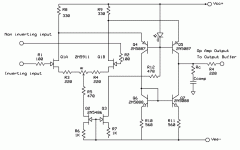
Thank you for the schematic. It simulates excellent, and the increased bias should be healthier for JFETs, as I'm told. Still the voltage drop over the LTP resistors is 1 V while the LED has a 1.7 V drop. I can't see why the drop should be equal though. In this circuit the voltage swing is reduced, but if I use two silicon diodes the voltage swing is close to within 1 V from rails.jam said:Nelsonvandel,
............don't give up now. The folded cascode is one of the best sounding gain stages I know.
This is what you need , well a good starting point anyway.
Jam
Yes, I've been interested in something like this and simulated some circuits. I can't get "that perfect curcuit", but I haven't used servos like you're suggesting, and not folded cascodes. Do you think this topology is better than a balanced amp? The nuber of parts will be almost the same I think.LineSource said:You may also want to Spice a supersym topology folded cascode with inv and non-inv output stages which can be bridged. The DC servo needs both +/- feedback, but can sum into one of the cascode current sources to null out DC, instead of summing to the input which seems to my ears to dull the dynamics
I think the ground channel(s) is of equal importance to the L/R channels, and I'm planning on using active ground one way or the other.
And yes Lineup , I guess I should increase the capacitance in a real circuit to have some margins, especially since I don't have an oscilloscope.
nelsonvandal said:
And yes Lineup , I guess I should increase the capacitance in a real circuit to have some margins, especially since I don't have an oscilloscope.
And you could test to remove emitter resistors, from JFET in input.
I would do it.
Does not hurt to do some comparing TESTs, does it?
....
1. Nelson Pass often omit those resistors. Or uses minimal values.
2. John Curl recommends run JFET without them!
He uses neither gate or source resistors, unless it is absolutely necessary!
Also he prefers to run his JFETs at a HIGH current.
What these 2 guys do not know about JFET, is not much.
They have used them in world class amplifiers, from the day JFET was invented.
( Which is not very long ago .. in human history )
Guys, it does seem that the VAS stage has very high open loop gain if used with a diamond buffer output stage.
Anyways to properly tune it down?
Also, I wonder how much of bias voltage (vbe drop) should we configure for the folded cascode VAS stage? (ignore it being portable)
EDIT: Is there any certain "rule" we must apply specifically for the vbe drops for the BJT cascodes? (it does seem to me that making it >0.7V would suffice but seeing circuits such as Beta22 from Amb which makes it a 12V drop instead makes me ponder why. It should not reduce output voltage swing am i right?)
Sorry for the long questions. I cant find these info in my textbook.
Hi,
most BJTs will go from just about turned off to saturated with a Vbe range of 400mVbe to 1000mVbe.
Going outside this range achieves very little.
For a BJT operating in lowish distortion amplifying mode, the range of Vbe will be much smaller, probably 600 to 650mVbe. The curves for this are in the datasheets.
^i'm aware of the inactive region, active region and saturation curve.
However http://www.amb.org/audio/beta22/schematic.html
It's weird that he uses 12V zener for the VBE drop. I thought normally one LED which gives about 1.6V drop would suffice.
What are the reasons for using a higher voltage drop?
However http://www.amb.org/audio/beta22/schematic.html
It's weird that he uses 12V zener for the VBE drop. I thought normally one LED which gives about 1.6V drop would suffice.
What are the reasons for using a higher voltage drop?
TzeYang said:Guys, it does seem that the VAS stage has very high open loop gain if used with a diamond buffer output stage.
Anyways to properly tune it down?
Also, I wonder how much of bias voltage (vbe drop) should we configure for the folded cascode VAS stage? (ignore it being portable)
EDIT: Is there any certain "rule" we must apply specifically for the vbe drops for the BJT cascodes? (it does seem to me that making it >0.7V would suffice but seeing circuits such as Beta22 from Amb which makes it a 12V drop instead makes me ponder why. It should not reduce output voltage swing am i right?)
Sorry for the long questions. I cant find these info in my textbook.
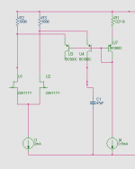
In december 2006, one and a half year ago,
I did a series of 'Clones' and Simulation designs of AD797.
The ultimate version was this:
High Voltage ( 100 V JFETs ) JFET input, AD797 Clone
http://www.diyaudio.com/forums/showthread.php?postid=1087124#post1087124
Look at my Attachment capture from circuit.
This is from a very good working version of my AD797 Clone.
It is a JFET input version, that was tested before I did my +-40 VDC version with high voltage JFETs.
Uses 2SK117, almost identical data to 2SK170, except from that 2SK117 can take 50 Volt.
I have chosen ~0.6 Volt drop across those 300 Ohm resistors
Because 0.5 mA x 1221 Ohm = 0.6 Volt.
The BC560C, U7, will give some temp compensation.
Regards, Lineup
Attachments
- Status
- This old topic is closed. If you want to reopen this topic, contact a moderator using the "Report Post" button.
- Home
- Amplifiers
- Headphone Systems
- Folded cascode headphone amp