Hi All,
This is my first post and i'm a complete newbie when it comes to electronics, so I have been working with a friend who knows far more than I. He suggested replacing a few parts on my crossover network, namely the sand resistor and tweeter/midrange capacitors.
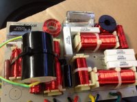
I did this, using V-Cap Oil, Mills Non Inductive resistor and a AEON cap.
The results of the modification were staggering. I'm extremely impressed with the results having a new found love for the speaker.
The next modification he suggested was replacement of L6, 4mh /0.43ohm ferrite core for a Copper Foil Air Inductor. He mentioned that the focal unit I had does a poor job of filtering high frequencies and would be distorting low freqs.
What are your thoughts on this? Due to the size and weight of the inductor, it would require its on board attached to the inside of the speaker.
I've attached a photo of my modified crossover and have a copy of the crossover network in pdf format (its a bit large to post)
Regards
This is my first post and i'm a complete newbie when it comes to electronics, so I have been working with a friend who knows far more than I. He suggested replacing a few parts on my crossover network, namely the sand resistor and tweeter/midrange capacitors.
I did this, using V-Cap Oil, Mills Non Inductive resistor and a AEON cap.
The results of the modification were staggering. I'm extremely impressed with the results having a new found love for the speaker.
The next modification he suggested was replacement of L6, 4mh /0.43ohm ferrite core for a Copper Foil Air Inductor. He mentioned that the focal unit I had does a poor job of filtering high frequencies and would be distorting low freqs.
What are your thoughts on this? Due to the size and weight of the inductor, it would require its on board attached to the inside of the speaker.
I've attached a photo of my modified crossover and have a copy of the crossover network in pdf format (its a bit large to post)
Regards
Attachments
I have Focal speakers but they are Chorus series not BE.
From what I know their are not the same problems.
BE series (double in price) have a smooth output frequency. The Chorus (not yours) are more of a commercial model (and taste).
So, here the amp (or preamp/equalization) should play a roll. Plus room et al.
The speakers should be adapted also. (I closed one of the ducts). And after one year or so bass is getting better. Tweeter too bright and to repair this dysfunction I use either shoulder pads (with an integrate amp) or a preamp equalizer.
Now to know the differences in/for better sound with your speakers, if you don't know what to look for, it's difficult to guess and because of that maybe it would be better to simulate or measure the whole thing.
Last edited:
Taking it as a test, and from the data available, shouldn't be a problem after all.
Different values (DCR it's identical anyway) might pose one, and/as if the original components and drivers were matched pairs and calibrated. But that's details you know at the end of the chain when they are measured on the factory floor. Nothing you need be afraid off.
What's the position of that inductor in the xo?
""Distorting low frequencies???" Maybe your friend knows more you telling us.
Taking it as a test, and from the data available, shouldn't be a problem after all.
Different values (DCR it's identical anyway) might pose one, and/as if the original components and drivers were matched pairs and calibrated. But that's details you know at the end of the chain when they are measured on the factory floor. Nothing you need be afraid off.
What's the position of that inductor in the xo?
""Distorting low frequencies???" Maybe your friend knows more you telling us.
When you say position, what do you mean?
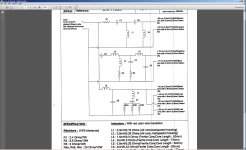
here is the layout, my friend suggested replacement of L6
Attachments
When you say position, what do you mean?
here is the layout, my friend suggested replacement of L6
The position physically near other parts can have interaction because they are too close together. An air core inductor will be far bigger than whats in there now so you may be better served locating if off the board away from the other parts.
Hi,
Well whist there is no harm in it I can't the see the point. An inductor that
is poor at filtering high frequencies ? If that is the case then probably all
the cored inductors on the board need changing. Distorting in the bass ?
Possible if its simply not big enough for the job, then get a bigger one.
rgds, sreten.
Last edited:
THERE YOU GO, use the same parts....he has done too

Lower DCR, stronger bass.
Less hysteresis, less distortion.
Bigger diameter of the wire (14ga) better the power (750W).
Copper Foil Coils | FoilQ | 14 Gauge | ERSE
Less hysteresis, less distortion.
Bigger diameter of the wire (14ga) better the power (750W).
Copper Foil Coils | FoilQ | 14 Gauge | ERSE
im not sure why you would want to switch to a lower DCR coil, when its likely the filter Q and response is optimised for the original coil DCR.
I can understand changing iron core for air core, but lower DCR is going to effect the response far more than anyother 'distortion', and that is what you will hear. Id stay as close to the original DCR as possible, regardless of core type. Just my 2 pence.
I can understand changing iron core for air core, but lower DCR is going to effect the response far more than anyother 'distortion', and that is what you will hear. Id stay as close to the original DCR as possible, regardless of core type. Just my 2 pence.
Last edited:
The thing I dislike most about L6 is that it's so close to a bunch of other inductors (core saturation and leakage flux). Since it is probably the highest current carrier (although this hasn't been proven?), it stands to reason that it should go first, if only to protect the others but it also suggests you'll get the earliest improvement with L6 and the new core.
I can't say I'm too concerned about lowering DCR in this case.
I can't say I'm too concerned about lowering DCR in this case.
It's not something you hear said about ferrite much, is it? Even the case for interwinding capacitance loses weight when you add a ferrite core, not that I'm being fair here.. but even so, by the time it is becoming a problem the woofer would be hardly able to draw a breath.An inductor that is poor at filtering high frequencies ?
Out of curiosity, would you mind telling me the values of C7 and L7?dastrix said:here is the layout
Last edited:
It's not something you hear said about ferrite much, is it? Even the case for interwinding capacitance loses weight when you add a ferrite core, not that I'm being fair here.. but even so, by the time it is becoming a problem the woofer would be hardly able to draw a breath.
Out of curiosity, would you mind telling me the values of C7 and L7?
Sure, they are
C7= 440uf/63V Non polar
L7=10.5mh/1.35ohm (Ferrite Core)
I guess im trying to improve the bass and im trying to work out what, if anything, would need to be replaced to do that. Keeping in mind I do not know anything about crossovers. Only using my friends asstistance who uses the Utopia Diva, not quite the same as mine.
AllenB, so you say L6 and the new core. Isnt that the same thing? ie, replacing L6 (a ferrite core) with either a wirewound or air foil replacement on a seperate board would net a improvement?
L6 in my photo of the crossover is actually under the large cap! Its the 82mm length one and visually looking at the board I think thats the largest unit on the board.
Last edited:
- Status
- This old topic is closed. If you want to reopen this topic, contact a moderator using the "Report Post" button.
- Home
- Loudspeakers
- Multi-Way
- Focal 927 Crossover modification