you can adapt part of this circuit:
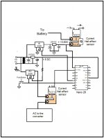
SCC2 10 Amp Solar Charge Controller
there is a zener + transistor circuit on the power input that cuts off power to the control circuitry below a certain input voltage to the charge controller. Or see the SCC3 schematic further in that site for another version.
SCC2 10 Amp Solar Charge Controller
there is a zener + transistor circuit on the power input that cuts off power to the control circuitry below a certain input voltage to the charge controller. Or see the SCC3 schematic further in that site for another version.
These will not harm the battery if solar power is used. If AC power is used an additional relay is needed to disconnect the charger since the charger schematics do illustrate several resistors from battery + to battery - for a ~1.3ma drain that would eventually drain the battery.
This device plus an added relay, looks pretty good for big solar!
Not so good for AC source
The desired "nap cycles" for the AC charger are similar to solar overnights; except that the AC charger doesn't nap reliant on the sun and thus AC charger wouldn't fall asleep at either the wrong time (dark) or the right time (charged). Instead, the AC charger will stay on, wasting electricity and also decreasing the lifespan of the battery. Solar, the energy is free and it naps every night, but AC needs more circuit for that since those charging features are not automatically provided by the AC power source.
Hello
You could get a Harbour freight float charger and modify it as per this Hacking a Harbor Freight Float Charger to get a upmarket charger with a float mode with temp compensation etc
I modded a harbour freight with good effect giving me rock steady 13.6v, with the mod you can set whatever float voltage you like.
Actually that was meant to read OR get an upmarket charger such as the Deltran battery tender or the one from CTK or any charger with a float maintenance mode, most of these these wait till the battery voltage drops below a predetermined level and then recharges the battery back to a certain voltage (hysteresis float charging) then "switches off" again and waits for the cycle to repeat, many of these types have temperature compensation built in, the harbour freight uses a different strategy, it "floats on the fly" and does not have any advertised temp comp as far as I know. Unless you live in a "wild" environment you can usually find a "sweet spot" charging voltage that will work across about a 30C temp range at least. There are many Float Charging Voltage vs Battery Temperature charts available on the net.
You could attach the module of the harbour freight float charger to solar panels, however you will need 15-16v @500-700ma to feed the float charger circuit.
You could attach the module of the harbour freight float charger to solar panels, however you will need 15-16v @500-700ma to feed the float charger circuit.
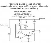
For the solar panel, I wonder about a DT relay and 2 zeners.
1
First the battery charger connects to battery through NC (when the relay isn't powered, the battery charger IS connected)
2
Next, the battery charges up to ~13.5v and a Zener energizes the relay, thus disconnecting the battery. This would be seriously annoying madly flipping relay except. . .
3
And, since its double throw, when it turned off the charger, it turned on a 12v zener (maybe 12v+silicon diode), which additionally turns on the relay so that it becomes stuck with the relay on, the battery charger off, until battery voltage falls below 12.7vdc, whereupon all relay power fails and that reconnects the charger.
It seems that this prospect would also work for AC charger since the relay in question could be DPDT, also able to cut off electricity consumption by one or two days at a time. When at less than 12.7vdc, there is ZERO standby drain. Perhaps a transistor is needed somewhere to assist accuracy? Ideas?
Hi,
This is just a suggestion that need more research. The idea it is to use a micro to control the battery charger and the converter. Attached is it an schematic showing more or less my suggested idea.
The battery charger will be control by the micro processor by checking the voltage to see if it at 13.5 if not then it will enable the solid state relay to charger it. The micro would continuously will monitor the current to see when reach a low current. At the beginning the battery current will be high once start charging the current goes low and the micro can turn it off. It will continuously monitor the voltage to be within limits. If it within limits it will turn off the relay or turn it on again .
Now the converter will be turn on by the switch and the micro will hold it enable. Once it is on then the micro will monitor the current until it goes down means nobody it using power and will turn it off. Nothing to it.
.
Attachments
The requirements of hysteresis, zero standby power and accuracy make the problem quite tricky.
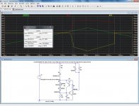
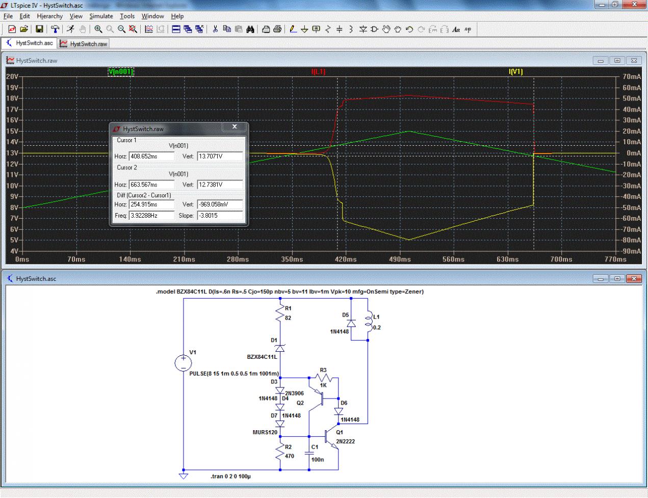
Here is an imperfect but near-enough solution, based on a pseudo-thyristor structure and zener.
The voltages of the zener and diodes have to be tweaked to adjust the thresholds: it is impossible to make something adjustable without spending current in a divider.
With the values shown, the thresholds are 12.7 and 13.7V, they can be tweaked by modifying R1, R2, D1, D3, D4, D7.
Below 12.7V, the current consumption is low, but non-zero, due to the imperfection of the zener.
Attachments
Elvee = Hero!!
This is great! The Normally Closed relay, L1, opens to disconnect the [over] charger after reaching 13.5~13.7v range when the marine type battery is definitely charged and then re-engages a day or two later as the battery falls to 12.7v? I'll give it a try as soon as I've sourced the parts.
This is great! The Normally Closed relay, L1, opens to disconnect the [over] charger after reaching 13.5~13.7v range when the marine type battery is definitely charged and then re-engages a day or two later as the battery falls to 12.7v? I'll give it a try as soon as I've sourced the parts.
That is the intended behavior. Be prepared to hand pick the zener if you want a very precise threshold.Elvee = Hero!!
This is great! The Normally Closed relay, L1, opens to disconnect the [over] charger after reaching 13.5~13.7v range when the marine type battery is definitely charged and then re-engages a day or two later as the battery falls to 12.7v?
As I said:I wonder if you could replace the fixed zener with an adjustable shunt reference like TL431. Then you could tweak the threshold.
In addition, the TL431 requires a 1mA current.it is impossible to make something adjustable without spending current in a divider.
It doesn't total to huge standby currents, but it is not a zero standby power circuit anymore.
With good quality, low current extra sharp zeners, the current consumption below the threshold can be negligible.
There also is a fascinating possibiilty: to use a transistor as a zener, but not simply between B and E: by connecting C and E in reverse, one benefits of the transistor effect, and this has funny consequences, for early planar transistors having substantial surface currents.
The "thing" behaves more or less as a diac, with a negative resistance characterisic.
This property can be put to good use to create hysteresis.
Quite conveniently, these older transistors have a B-E breakdown voltage of a little over 6V, and a nice snap-action negative resistance spreading over 0.6V: ideal to make a true zero standby threshold relay.
Examples of such transistors are 2N708, 2N2926, etc.
Some more modern power transistors have a higher breakdown voltage, around 12V; one would be sufficient.
A lot of testing and tweaking is required, to find devices having the right voltage and hysteresis, but once found, they allow for a "perfect" circuit.
The schematic below has been tested, but not simulated: the models are not complete enough to simulate the negative resistance effect.
Attachments
The leakage current in the batteries is one or two orders of magnitude greater than that. Even if powered by these batteries, 1 mA standby current is negligible. The ease of adjustment is probably worth it, but only Daniel can say.As I said:
In addition, the TL431 requires a 1mA current.
It doesn't total to huge standby currents, but it is not a zero standby power circuit anymore.
The leakage current in the batteries is one or two orders of magnitude greater than that. Even if powered by these batteries, 1 mA standby current is negligible. The ease of adjustment is probably worth it, but only Daniel can say.
The adjustment sounds necessary for when solar and AC are both used and for when you'd like to have the solar prevent/block using AC (two different sets of very close settings). For sure there's no problem using adjustable in the solar application. For AC, the problem, 1ma, is so very tiny I'd just have to try and see what happens if the cord is left unplugged for a month or more.
P.S.
For the solar application, it would be interesting to "pay back" the 170ma relay drain by bypassing the relay contacts with a resistor to dramatically decrease current instead of disconnecting the solar panel. A 30w solar panel could harm a battery, but a 5w solar panel won't do that (and we probably don't need 5w to compensate for that 170ma relay; however, the 5w is a "bright sun" figure). About what estimated resistor value do we need? This would help keep the cycles nice and long. . . which would also prevent the AC charger from switching on.
P.P.S.
How to "knock out" standby current drain for solar application at night? I thought of using a cap parallel with a reed relay coil to detect voltage at (directly at) the solar panel and thus turn on the rest of the circuit as needed, but this wouldn't last long since in dusky light that reed relay would rapid cycle and wear itself out.
Last edited:
The problem with negative resistance is that it turns every resonator it's connected to into an oscillator. You probably want local damping. local negative resistance from something like a transistor junction could easily produce RF burst at high RF. I suspect that's why negative resistance is not in widespread use.
Also look at the PEMZ7 Ib-Vce curves, that's negative resistance no?
Also look at the PEMZ7 Ib-Vce curves, that's negative resistance no?
No, not in this case. Ever played with neon bulbs, diacs, open base transistors? (I mean physically, not in sim)The problem with negative resistance is that it turns every resonator it's connected to into an oscillator.
It's fun, lets you create really minimalist oscillators and is much too slow to cause HF oscillation problems
There does seem to be a moderate negative resistance effect, but I don't know the cause.Also look at the PEMZ7 Ib-Vce curves, that's negative resistance no?
With the open base, it happens at the breakdown voltage, but here it is different: it manifest itself by decreasing the current at increasing voltages, whereas a breakdown causes a decrease in voltage for increasing currents.
The difference may look subtle, but it is important.
I wonder if their spice model reproduces the effect.
Transistor finding. . .
In regards to this circuit (post 27), I have the NPN (a metal can 2N2222) but not the PNP and the order for 2N3906 fell through, so before trying that again, can I use any of these amplifier parts instead of the 2N3906?: Phililps BC556B, NXP BCP53, Philips BD140, Fairchild BC556C, Fairchild KSA992F?
Thanks!!!
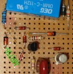
Photo, and additions
This has BC556C with 2N2222. D7 has been shorted to achieve 13.5vdc. On the left are the additions, because there was only 1/10th volt float range, so to achieve the float/delay function I added an additional copy of R1 (180R this time) D1, D3 (MR this time) and D4) and this additional, slightly lower voltage copy of the sensor is switched ON by the reed relay. This addition bypasses/parallels R1+D1 whenever the relay is switched on. The reed relay also switches a larger relay (not pictured). The additions were a guess that happens to work for 12.67vdc to 13.54vdc range. Did I do it right?
This has BC556C with 2N2222. D7 has been shorted to achieve 13.5vdc. On the left are the additions, because there was only 1/10th volt float range, so to achieve the float/delay function I added an additional copy of R1 (180R this time) D1, D3 (MR this time) and D4) and this additional, slightly lower voltage copy of the sensor is switched ON by the reed relay. This addition bypasses/parallels R1+D1 whenever the relay is switched on. The reed relay also switches a larger relay (not pictured). The additions were a guess that happens to work for 12.67vdc to 13.54vdc range. Did I do it right?
Attachments
Daniel, I got 10+ years (still going) on a bank of FLA batteries even through New England winters with this float charger. I think holding the voltage right up against the self discharge is the recommended way. This circuit never draws more than the self discharge current no matter what the source. The source of float and bulk charge are isolated to allow maximum versatility.
Attachments
Last edited:
The delta between voltages is normally set by D3/D4/D7: by substituting smaller or larger devices or adding one, you can adjust the hysteresis.This has BC556C with 2N2222. D7 has been shorted to achieve 13.5vdc. On the left are the additions, because there was only 1/10th volt float range, so to achieve the float/delay function I added an additional copy of R1 (180R this time) D1, D3 (MR this time) and D4) and this additional, slightly lower voltage copy of the sensor is switched ON by the reed relay. This addition bypasses/parallels R1+D1 whenever the relay is switched on. The reed relay also switches a larger relay (not pictured). The additions were a guess that happens to work for 12.67vdc to 13.54vdc range. Did I do it right?
Anyway, if you have achieved what you aimed at, that's the only thing that counts.
Scott's proposition looks sensible, if you are prepared to jettison your relay
- Status
- This old topic is closed. If you want to reopen this topic, contact a moderator using the "Report Post" button.
- Home
- Amplifiers
- Power Supplies
- Float charger? Cut off at 13.5v rest until 12.5v before switch on?