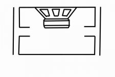
Here's the basic concept of invisible or magic ports for you. Basically the only neat thing about them is that you can look directly through the box and not into a black hole. So they look like they're not actually ports, but they are.
Its easier to fit a slot port into the box because you can actually build them into the box. True it takes up much more volume(3/4"MDF is much thicker than 3/15" thick PVC and of course a circle maximizes area for a certian perimeter) But if the box volume and how it is built are of no issue(One thing more common with DIYed designs) then it will be cheaper fitting a 10 foot slot port into a box than a 10foot PVC port
Its easier to fit a slot port into the box because you can actually build them into the box. True it takes up much more volume(3/4"MDF is much thicker than 3/15" thick PVC and of course a circle maximizes area for a certian perimeter) But if the box volume and how it is built are of no issue(One thing more common with DIYed designs) then it will be cheaper fitting a 10 foot slot port into a box than a 10foot PVC port

paulspencer said:Rabbitz, how does distortion come into it?
Port noise = distortion
Hi,
Check this:
http://www.haliaetus.com/va/haliaetus.html
In technical area you can play with a knob to see the effect of port non-linearity.
"Horn shape duct" in "loudspeaker" forum also deals with this.
@+Maiky
Check this:
http://www.haliaetus.com/va/haliaetus.html
In technical area you can play with a knob to see the effect of port non-linearity.
"Horn shape duct" in "loudspeaker" forum also deals with this.
@+Maiky
Very interesting. Their diagrams depicting turbulence appear to be about as accurate as those from the B*** marketing dept!
It looks to me as if it would be LESS effective than a regular flare, as it doesn't really tackle the problem of boundary separation at high velocity very well IMO. Instead it slows down the velocity by causing the rapidly moving air to increase in cross sectional area. However, at the exit there will still be eddies caused, and they would be worse than those of a regular flare if not for the fact that the velocity at this stage has decreased. Looks to me more like a showy solution more based on cosmetics than function.
Also the volume of the sub box is tiny for a vented box intended to get down to 20 Hz! There is no room for a vent, so I don't know what that thing actually is! Aperiodic? Doesn't seem like that is their intention ...
They talk about it as if it is some kind of dipole, with their mention of directional bass ...
I think it's more novelty than engineering, but perhaps someone else can shed some more light on this ...
Hi,
I don't want to be too rough be I think you're misled by the common marking habits of the fancy brands.
Those guys do have a very (very) advance engineering policy. They belong to one of the most famous public research laboratory (http://www.lam.jussieu.fr/) and collaborate with the Ircam (http://www.ircam.fr/?L=1 created by Pierre Boulez...) and are highly regarded as academics. They are pure researchers that try to make effective speakers. Just read the AES white papers be convinced. Actually the speakers you saw are only for the” fun” and show their utmost in speaker design : check the enclosure, the cross-over DSP based, and believe me , I am an engineer in mechanics (structure & fluids) specialized in acoustics … those guys know about architectural acoustics! In addition they all have kept their job in the laboratory…
Anyway the use of a nozzle should not be to bad for high speed air flow as it is used in rocket boosters where one cannot afford any uncontrolled air flow turbulences, They do comparisons with cylindrical tubes, as far as you can compare them…
The nozzle in this case, deal with very low frequency and they make a dipole directivity pattern for their sub. You can check www.linkwitzlab.com to have more details.
They smartly use the BR behaviour around the Fb to increase the low extension. The points of using a nozzle are
- to drastically reduce the air flow noise cause by port under high air speed conditions
- to convert the kinetic energy of the air flow into the potential energy of the pressure sound wave (the inverse of the high speed water cleaner Karcher) because pressure is what we hear….
- for subs the Dipole pattern is very efficient to help with egen modes in architectural acoustics.
@+
Maiky
This is similar.
An externally hosted image should be here but it was not working when we last tested it.
I don't want to be too rough be I think you're misled by the common marking habits of the fancy brands.
I think I deserve FAR more credit for intelligence than that. If you want to make a statement like that, at least back it up rather than making broad sweeping statements like "these are highly regarded experts ..."
I raised some specific issues. Rather than respond to them in a specific manner you make only general statements.
I have not been misled by any "common marketing habits" which should be obvious. I see this company using misleading animated diagrams, which do nothing to help their credibility. In particular look at their diagram showing eddies caused by high velocity air movement in vent flares vs their nozzle. The airflow within their nozzle is shown to be perfectly laminar, following the profile. Within the flare, it is shown as moving in a straight line as if the flare does not exist. The flare rate of their nozzle is more gradual, hence it will remain laminar within the nozzle at higher velocity, however at the end of the nozzle the performance will be much less than that of a regular flare at its termination. As shown by Collo's experiments, the velocity would have to be low at this point to avoid chuffing, as at that point it would be like a very large unflared vent. At this point is relies purely on size to reach its performance goal. I would expect better performance of a regular flare of the same size.
So how is this misleading?
1. First look at the diagram with knob at position 2. The flare profile at this point is almost identical, yet theirs is shown with laminar air flow, while the regular vent is shown with eddies.
2. At position 4 on the knob, the air from theirs moves out in straight lines past still air, yet no eddies are shown! This is precisely how turbulence occurs in unflared vents!
3. Theirs is shown with many more arrows, where the regular flared vent is shown with less, so that they can draw exaggerated large eddies, and not really give an accurate visual comparison
In short they have selectively exaggerated the weaknesses of the conventional design, while hiding their own. But who am I to question the rocket scientists!?
One thing to keep in mind is that a rocket outlet is not the same thing as a subwoofer vent. The latter usually is a hole in a baffle of much larger dimensions than itself. Hence the best way to reduce turbulence is to aim to get the air to follow a flare which spreads out its direction of travel.
The nozzle is a solution more suitable for a vent which terminates outside the box. I would expect its performance could improve with a regular flare on its termination, which could reduce the necessary length.
- to convert the kinetic energy of the air flow into the potential energy of the pressure sound wave (the inverse of the high speed water cleaner Karcher) because pressure is what we hear….
Can you elaborate on this a little more? If sound waves travelling in a vent are considered as kinetic energy, how are they converted to potential energy? Lift an object up into the air and you give it potential energy, which is then turned into kinetic energy as you let it descend with acceleration due to gravity. To convert this energy back into potential energy, it would have to bounce back up off something until the point where all its kinetic energy has worked against gravity and it then only has potential energy just at the point before it falls again.
- for subs the Dipole pattern is very efficient to help with egen modes in architectural acoustics.
The nozzle in this case, deal with very low frequency and they make a dipole directivity pattern for their sub. You can check www.linkwitzlab.com to have more details.
I'm familiar with dipoles and with Linkwitz' work on them.
They appear to show measured polar response which is interesting, and their comments suggest they have found a way to control directivity from 20 - 40 Hz, achieving a quasi dipole radiation. Unfortunately this is the region where monopole radiation is most appropriate! Dipole radiation is more useful in the 40 - 200 Hz range!
I had some more thoughts on using a smaller flare on the inside end of the port. We are dealing with air that is bi-directional.
As Homer would say: "Air goes out, Air goes in, Air goes out...."
Air exiting a port flare needs to expand with the flare to avoid turbulence. Air entering a port flare is probably better behaved because it should be constrained by the pressure increase.
If correct, this would mean that a flared port would be less likely to have turbulence problems as air enters the flare
For a flare on the inside end of a port, the most turbulent part of the cycle would be when the air is flowing back into the box. This inflowing air would help to mask any turbulence generated by an undersized flare inside the box.
Ok let's go...
1. Sorry, as you said I was in only saying words of wisdom, I should have had "this doesn’t regard Paulspencer". I have never put your intelligence in question, I don't know you. But you are right when you say" least back it up rather than making broad sweeping statements like "these are highly regarded experts ..."".
But actually they are. I meant: they do have a scientific background. That's all.
I know that these speakers have a strange look and engineers have very strong claims, like many other companies (who think about B&W?). Some actually deserve to be considered some don't. IMHO this one does, and yes when I say IMHO I keep on being and acoustical engineer. They are neither shamans nor gurus. That was my meaning when I wrote “experts”. They are researchers in Acoustics not in Rockets even if ESA supports them… Did you check the links I gave? Maybe receiving a price for been a very good violin player and study the fundamental physics of instruments and architectural acoustics is not enough for being an expert in acoustics.
2. Technical
a) “Flares are almost identical”: totally false. But if you haven’t studied nozzles, it is difficult to know that. Flares like you describe haven’t inflection points mathematically speaking. The flares have a high ds/dx means the expansion is fast leading to instabilities (from mechanics of fluids point of view). A nozzle has one, precisely at position 2, the dS/dx is stronger and stronger for exp(x) type flares and is smaller and smaller for nozzle. This is the point of using a nozzle
b) In this case, this is especially the aim of a nozzle to decrease the flow speed and orientate it so that turbulence are the less likely to occur. At least if the nozzle has been design in the rules of the art.
c) Ok let’s run Fluent and see what happens… It’s joke I haven’t the time to do so.
Any way if the flow is slow enough the Reynolds number is small enough to avoid instabilities (again from mechanics of fluids point of view).
A small picture, “with the hands” as we say in French, of what happens in the nozzle.
During the expansion in a small portion of the nozzle:
S area, V speed dt : delta time
K are >or = 0 P pressure Po is a constant > 0
The flow is conserved:
V1S1dt=V2S2dt thus
V2=V1S1/S2
Euler, Navier Stokes & al point out that energy is conserved:
V²/2 + P/Po = K
Leads to (logarithmic differential)
dP/P = 2dV/V
Thus P2>P1 since S2>S1
I hope it is clear enough for the energy transfer.
More precisions.
The explication following are based upon mathematical analysis a bit hard to be explained because of integral calculus.
When you change the profile of a vent the quantity that should remain equal is the acoustical mass. Basically the general formula is something like that:
] rhodx/dS(x) Rho air density ] integral
For a classic bass reflex the nozzle permit to have a small enclosure with a low tuning frequency with a small port and high linearity. Let’s try to calculate the length of the vent for a 40L sub tuned to 20Hz with a linearity as good as the nozzle. You’ll have a vent of 1m or so the nozzle would be much smaller.
For a the directivity pattern at low frequency, the point is to increase low frequency range, in theory the limit is 0hz with a very small roll off and a low THD. I remind you that any ported (including passive radiators) has a THD that explodes under the driver Fs what ever the port...
I hope I have answer to your specific points
Best Regards
@+
Maiky
PS:
Just to say that the gravity effects are taken into account in the relations I quoted and it is a matter of a special derivative regarding a particule of fluid.
The term is grad(P). But to be honest I don't want to redo my degree in M of F onthis forum. Because I don't know if everyone want to learn how to do a gradient a rotational (vorticity) or the divergent of a particul in vertorial calculus... I just make things easier enough for everyone to understand.
PLease refere to books in case you want more detailed theory.
@+
Maiky
I have no idea what you are talking about..... I'm not being smart as I have no idea. Please take no offence in that comment as I'm just thick and not in my field of engineering.
What I would like to say, does this increase the case for sealed subs with drivers that can go down to the required frequency with out any assistance from ports, passive radiators or electronic means. I know that there is a drawback with the increased excursion in sealed but surely would have far less distortion than ports which I imagine will distort into double digit numbers.
Anyone like to comment on this from experience.
I haven't had time to do a proper response to Maiky's more detailed post. This quickie is all I have time for right now ...
Rabbitz, I have seen a review of about 15 comercial subs where they were all measured for frequency response, power compression, SPL and distortion. The sealed subs had higher distortion than the vented subs. The only sealed sub that managed to achieve very low distortion was an 18" Velodyne servo sub. Overall a properly designed port should reduce distortion significantly. I can find a link to the review if you are interested. It's also interesting to see actual power compression measurements of subwoofers, which is not often available information.
Consider this: you have to design a commercial subwoofer to achieve a certain SPL at 20 Hz with a given budget. You can make it either sealed or vented. If you choose sealed, the driver must have twice the excursion, the amp has to be able to supply the power to do it (more cost), the driver has to be able to handle the extra power (more power compression). Since this requires a more costly amp, you have to spend less on the driver, but at the same time the driver needs to handle more power and more excursion! By contrast, the vented sub will have a much better driver, perhaps with an XBL2 motor or something similar and shorting rings. It will be a bit bigger, but will have far lower distortion. The sealed sub would probably need a servo, adding extra cost, to try to achieve low distortion, and if it's possible to pull this off with the same budget, then it really is a tribute to servo subwoofers!
I noticed that as well, I don't know why they did, but I have heard a $2k 10" sub that was a B&W and at the time it did sound quite good, very tight sounding, although with the driver moving a lot it was only just loud enough to reach moderately loud levels on music.
Check this out:
http://www.ultimateavmag.com/features/604way/
That is the link ...
The Bagend with a 21" driver and 1"xmax has THD over 20% even at moderate levels! The Kleiss is not much better. The Triad also has more than 20% THD @ 100 db! The Revel gets well over 30% at 105db!
The vented subs measure much lower. The Snell is less than 5% at these levels. The Adire Sadhara is also very low except for at 20 Hz, which I'm told (from Adire) was due to a rattly old box. The Genelec has distortion VERY low, above 40 Hz its the kind of distortion figures you might not get with mains easily! ~3% @ 100 db!
Collo,
That's great work, thanks for sharing your results. Like Ron, I recommend near field work to avoid the difficult translation from room results. For example, room presurization is very dependant on room size and boundary losses, so the conversion factors are very hard to accurately determine.
Here are a couple AES preprints you may want to read, if you'd like to investigate ports a bit further:
1. preprint #3999, The Nonlinear Behaviour of Reflex Ports, Juha Backman
2. preprint 4523, Loudspeaker Ports, John Vanderkooy
Backman explored the compression, turbulence and distortion of various ports. He shows the formula for flow resistance through a circular pipe, shows impedance measures describing how a vented box approaches a sealed at very high levels, and how noise and distortion trade off with each other at various levels, all with real measurements. Compression 9ie linearity) THD (i.e. port resonances) and THD+N (i.e. resonances+turbulence) are shown vs. level for straight pipe, one end flanged, 2 ends flanged, slash cut vents, elbow vents, 90 degree vents, 15mm radius, and rigid foam on one vent end.
The data itself is good for reference, but not as a study for flared ports. He experimentally shows the real degradation with non straight vents, how truly bad no radius is, and the benefit of radiusing both sides.
The Vanderkooy paper looks specifically at flared ports. A few points from it:
- non symmetrical ports can lead to pressure differences between the inside and outside of the box, causing static driver displacements while in use that lead to more distortion, due to BL asymmetry
- shows how a cosh flare reduces compression and 2nd order distortion
- shows how long flared ports are lossy
- good advice that measuring a port near field should not be directly in front, or the turbulence will impact the mic diaphragm and give false results
Mind you, much of Vanderkooys results are found in preprint 4855, so if you need to get only one, get 4855.
Thanks again for sharing your test results.
Dave
- Status
- This old topic is closed. If you want to reopen this topic, contact a moderator using the "Report Post" button.
- Home
- Loudspeakers
- Subwoofers
- Flared ports and turbulence