I bought a pair earlier in the year but a screw up with the test rig I cobbled together fritzed one .... sux I know. I was planning to use them for an Aleph J but the store's board layout doesn't really lend itself to a straight forward fit from this style of component. One for the learning curve on my part.
Following that learning experience, I got myself a Peak DCA75. The unit was purchased without a calibration certificate but (according to Peak) all units are calibrated as part of the production QA process.
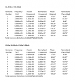
Refer the attached for the test runs that I logged of the surviving 2SJ109. There are 2 files. The A and B files relate to the respective JFETs in the monolithic component.
From use with the tester, I observed that there was little bit of drift in the results associated with subsequent tests. So, I ended up logging the results of the 5th consecutive test. That seemed to give stable results.
Best efforts to help but please be aware that I'm not a electrickery techo wunderkind.
My read of the results are that the component that I tested is legit. Here are the summary results (sheet marked "ID" from the attachment):
If I've misunderstood the data, I'm sure that those who know more will chip in with their advice.
Hope that helps..
Wow,thanks for the detailed answer!It will help me and others as well.
Does anybody have any unmatched 2SJ109s lying around? I bought out the stock of a bricks-and-mortar ham radio shop that was closing down, but they only had 13, and that turns out to be not quite a big enough pool.
I wouldn't mind having a few more in the kitty, but I'd also be willing to just pool resources, match them, and then split them back up if anyone is interested.
FWIW, my 13 as measured on a Peak DCA at room temp:
6.8
7.0
7.4
7.6
8.0
8.0
8.5
8.8
9.3
10.0
10.1
10.4
10.5
which gives me 3 nice pairs and another two decent pairs, but it still leaves some without a partner.
Cheers,
Jeff.
See post 181 Interest for genuine Semisouth SJEP120R100 curve tracer matched pairs & quads Patrick to the rescue 
So here's another question on the 2SJ109's. How close do they need to be?
For distortion we're using the matching within the 2SJ109 (each one lies across the LTP, rather than forming a leg of the LTP).
But what about within the leg? Do we need to worry about current hogging, or can the two 2SJ109s be completely unmatched?
Thanks,
Jeff.
For distortion we're using the matching within the 2SJ109 (each one lies across the LTP, rather than forming a leg of the LTP).
But what about within the leg? Do we need to worry about current hogging, or can the two 2SJ109s be completely unmatched?
Thanks,
Jeff.
So here's another question on the 2SJ109's. How close do they need to be?
For distortion we're using the matching within the 2SJ109 (each one lies across the LTP, rather than forming a leg of the LTP).
But what about within the leg? Do we need to worry about current hogging, or can the two 2SJ109s be completely unmatched?
Thanks,
Jeff.
Would LT Spice offer useful insight?
Bear with my ignorance of the software - I don't know how easy/hard it is to define the key criteria - but my thought is that it may reveal this sensitivity. Maybe not. There's always going to be the immeasurable aspect of how it sounds, anyway.
I'd be interested to read Nelson's thoughts on this point.
This is what Spice says.
(The DC offset was re-trimmed with Idss offset, without saying.)
Negative feedback came to the rescue.
I do expect Yfs mismatch to cause more distortion than Idss.
But it's your turn.
Patrick
.
Electrickery Engineering is not my forte but I'd say there's a gnat's_4skin difference between those numbers. Nice bit of spicing EUVL.
Patrick,
If we like more power and drive for 6 ohm speakers would you approve paralleling second output pair using for example +-27 V rails and 2A total bias
If we like more power and drive for 6 ohm speakers would you approve paralleling second output pair using for example +-27 V rails and 2A total bias
I wanted to know whether I can adjust the schematics such that it can be optimised to drive a 3R load without parelleling output devices.
Well, you can, by changing a few things, including to 16V rails and 2A bias.
And it would be useful also for 8R loads, even up to 10Vrms output.
Cheers,
Patrick
.
For those who want to experiment without paying for unobtaniums, take a serious look at this :
https://www.diyaudio.com/forums/hea...borberly-eb602-200-revisited.html#post5913588
Patrick
https://www.diyaudio.com/forums/hea...borberly-eb602-200-revisited.html#post5913588
Patrick
On the topic of LTP device matching:
In Patrick's analysis the ratio of 2nd to 3rd also deteriorates, but it's still only a couple of dB.
My main concern was current hogging. Let me poke on that a bit with my somewhat limited understanding.
Given that the two halves of each SJ109 are reasonably balanced (and thermally coupled), the worst that can happen is that one SJ109 gets all the CCS current divided between its two halves. That's still well within its normal operating range, so no big deal.
But that begs the question of why have two anyway? Nelson indicated it was to get more front-end bias and more transconductance.
I take this to essentially mean more gain. More LTP current delta for the given input voltage delta, meaning more current and therefore voltage drop over the potentiometer, and therefore more bias at the SemiSouth's gate?
So if one SJ109 is hogging all the current from the other (at equal voltage), then it must also be hogging all the transconductance. In other words, it's giving us the doubled-up transconductance all on its own. So again, we're good.
Is this a reasonable description?
Thanks,
Jeff.
> Is this a reasonable description?
If you believe in Spice, that I have already demonstrated that it makes little or no difference.
For the same Vgs of the Semisouth, doubling the frontend current only reduces the drain resistor value.
So what you gain in Yfs, you lose again there.
That would be my intepretation.
I am sure Nelson has a different one.
Patrick
If you believe in Spice, that I have already demonstrated that it makes little or no difference....
But I assume you ran SPICE with a default (constant) temp, no? So it won't have modelled current hogging (assuming any exists). Or do I have the wrong end of the stick?
Thanks,
Jeff.
- Home
- Amplifiers
- Pass Labs
- FirstWatt J2