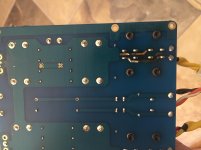
I would also consider increasing the voltage for the higher output power (if needed). Mine is singing without any problems last several years at secondary TR voltage of 2 x 22V. The included picture is old, now it is run as dual monoblocks in identical case and with second PS.
http://www.diyaudio.com/forums/pass-labs/186848-babelfishing-mighty-ar2.html
http://www.diyaudio.com/forums/pass-labs/186848-babelfishing-mighty-ar2.html
I would also consider increasing the voltage for the higher output power (if needed). Mine is singing without any problems last several years at secondary TR voltage of 2 x 22V. The included picture is old, now it is run as dual monoblocks in identical case and with second PS.
http://www.diyaudio.com/forums/pass-labs/186848-babelfishing-mighty-ar2.html
That's handy information.
What is Vds across and current through input jfets on your build?
That's handy information.
What is Vds across and current through input jfets on your build?
I hope ZenMode would remember or know. It has been really long time we did it. I would be glad to make a reading and let you know, but I am flying tomorrow morning on a short trip and will be back on June 14th. If Zen cannot figure it out until then, I will measure and post answer here upon my return.
If I could point on something, my problem was that I did not install in the first place the right sized LEDs, and after we corrected for it, all was fine. So read carefully about LEDs and purchase exactly the one specified.
Power is not really a problem but if the extra voltage gives them a sonic edge then, why not?
Even though I see the mighty ZM holds you in HIGH regard I will wait to get his permission for such a thing. He knows my limitations ...
Thanks for the idea.
No sonic edge due to the higher voltage, just more power.
I would also consider increasing the voltage for the higher output power (if needed). Mine is singing without any problems last several years at secondary TR voltage of 2 x 22V. The included picture is old, now it is run as dual monoblocks in identical case and with second PS.
http://www.diyaudio.com/forums/pass-labs/186848-babelfishing-mighty-ar2.html
I think that rickmcinnis plan is to build separate psu but still utilizing same chassis. Increasing psu voltage will be toooo hot for factory chassis, unless current draw is reduced, which is not an easy task on original J2.
hmm, back to my first suggestion, keep your original J2 and build a clone if you want to jump into real DIYaudio. then you can play with manyyyy iteration and possible permutation with your wildest mind. but again as gerd has mentioned, will it be better then J2 which is cooked by the master?
......
ZM - I just realized those simulations are using a stepped load for the current source. You might want to change that.
nope , just checked - it's plain simple 1A65 CCS
......
Even though I see the mighty ZM holds you in HIGH regard .........
not just that
ZM is AR2's Padawan
")
however - important difference - what AR2 is having (as somewhat more potent iteration) is Babelfish J2 , which is having cascoded front end LTP , meaning that input JFets are having voltage (thus dissipation ,too) umbrella ; factory J2 is not having that , so upping rails voltage would be as howling a Devil , especially taking in account that in your J2 there also are JFets as small CCS for input LTP, connected across entire rail
Papa did that few times , but I wouldn't ..... me being cheapskate and woosie

Last edited:
So the resistor input supply has a little more ripple but you lose a capacitor in a position that makes the rectifier work harder than it needs to along with the fact that the resistance makes life easier still on the rectifier.
I think that is the one I will build first.
I agree one needs to build something!
I think that is the one I will build first.
I agree one needs to build something!
not so sure that your problem lies there
You are correct, my four diode bridge failed as a short! Time to regroup!
I don't know how much influence that Stereophile has today, but it is nice to see FW review on this magazine. Their measurement part is always interesting. Thank you.
- Home
- Amplifiers
- Pass Labs
- FirstWatt J2