Hi,
I got it running. The sound is very good, but there is some hum.
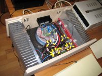
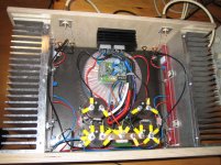
My setup: 800VA transformer, 4x 47000uF, 2 Bridge rectifiers, CRC as in manual.
The switch on is with a switch-on-unit (resistor, delay, relais), the ground connection with 10R, 2Diodes from a bridge and a small film cap (100nF or so...)
The two supply voltages meet in a single point - the copper bar.
If I switch off the transformer, the hum immediately stops. If I source the power with the lab supply, there is no hum either. I connect the lab supply ground as well to the 220V inlet ground.
How can I solve the humming trouble?
Regs, Dirk
I got it running. The sound is very good, but there is some hum.
My setup: 800VA transformer, 4x 47000uF, 2 Bridge rectifiers, CRC as in manual.
The switch on is with a switch-on-unit (resistor, delay, relais), the ground connection with 10R, 2Diodes from a bridge and a small film cap (100nF or so...)
The two supply voltages meet in a single point - the copper bar.
If I switch off the transformer, the hum immediately stops. If I source the power with the lab supply, there is no hum either. I connect the lab supply ground as well to the 220V inlet ground.
How can I solve the humming trouble?
Regs, Dirk
Attachments
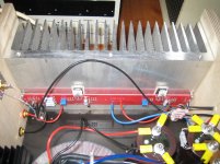
Another Problem: I cannot rotate the toroid: It's fixed with 2 screws!
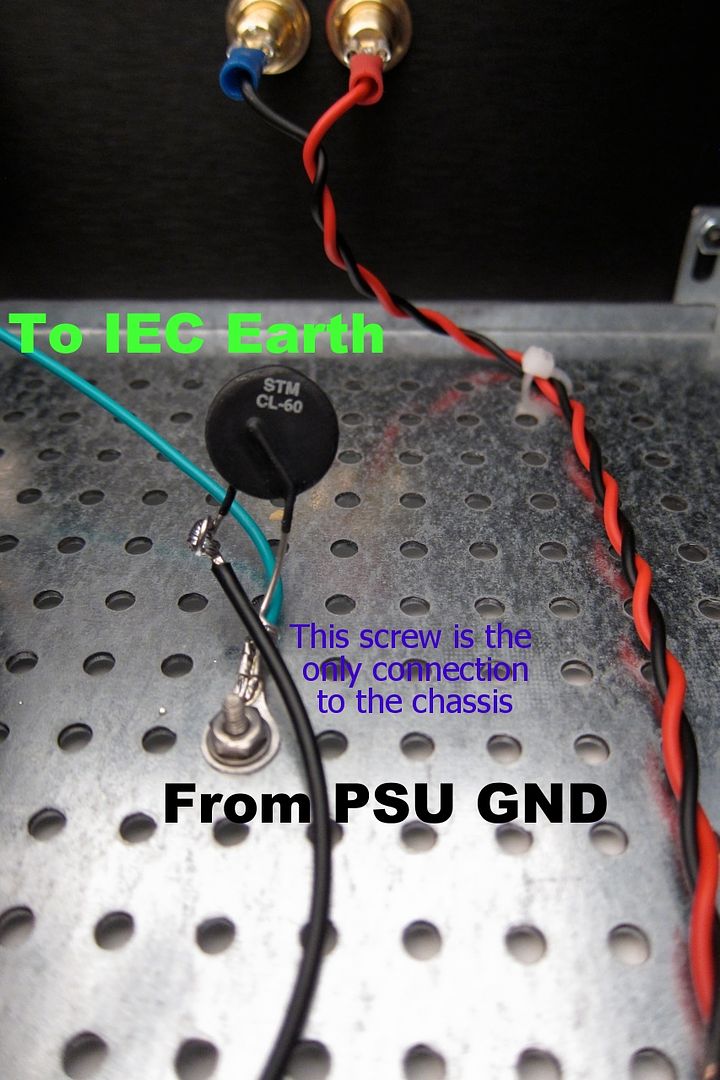
Is the metal plate (under the pcb on top of the toroid) grounded, or connected to the pcb electrically in any way?
Exactly how is the toroid mounted - you said there are two screws?
")
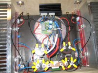
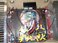
I have to wonder if you wouldn't be better off removing the speaker return ground wires from the channel board and running them directly to the grounding bar.
Also your main filtering cap bank would be ideal for a central ground plate mounted between them. This would put all four of the main caps at the same ground plane. Right now you have two of the caps connected to the ground bar directly and two connected via wires. With the central plate between them you could still mount your chassis ground isolation rectifier underneath the plate the same way you have it mounted to the bar now.
Also your main filtering cap bank would be ideal for a central ground plate mounted between them. This would put all four of the main caps at the same ground plane. Right now you have two of the caps connected to the ground bar directly and two connected via wires. With the central plate between them you could still mount your chassis ground isolation rectifier underneath the plate the same way you have it mounted to the bar now.
I see 5 bolted connections into what looks like PSU Zero Volts............. but there is some hum...........
You MUST remove the 3 middle connections and make just ONE.
Then some short or long distance away from that ONE middle connection, make your tappings for all your Zero Volt references.
NEVER put your reference along the capacitor charging bar/wire/trace.
You have many wires that are NOT Close Coupled.
You MUST SORT this error.
Every wire pair of Flow and Return must at least be close coupled along their whole route. Even better if you make these twisted pairs along their whole route.
Last edited:
#10: Transformer mounted with 2 big V2a screws (M5 or M6), the Metal Plate attached to the screws. Not grounded.
#11: This contradicts the ideaof a well tied ground...Any opinions on this?
#12: Will try. difficult to reach the point mechanically. Hopefully on wednesday.
#14: I think, My solution is inferior to yours, but better than a PCB...
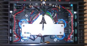
#15: I think, I didn't get the point. I thought, even my setup (1 pic) was ok.
Now to repeat my biggest problem in understanding:
If I have the amp as shown in Pic 1 (no ZENMod modified), it was dead quit, if I used my lab supply and had the power transformer switched off.
I did the following:
Just had two floating suplies connected after the rectifiers,
Had the ground of the lab supply connected to the ground on the net plug.
So in principle the grounding scheme was exactely as before, but no hum a all.
So for me the explanation would be: If I supply clean DC, nothing is wrong. I would now guess, that if I connect the lab supply and load the internal transformer, the hum will be back.
So I should run a test with the transformer loaded with a dummy and the lab supply.
Please tell me, how the lab supply can work this way, but the r-core troubles me.
Any Idea, what I can use to load the transformer with 2,6A???
#11: This contradicts the ideaof a well tied ground...Any opinions on this?
#12: Will try. difficult to reach the point mechanically. Hopefully on wednesday.
#14: I think, My solution is inferior to yours, but better than a PCB...
#15: I think, I didn't get the point. I thought, even my setup (1 pic) was ok.
Now to repeat my biggest problem in understanding:
If I have the amp as shown in Pic 1 (no ZENMod modified), it was dead quit, if I used my lab supply and had the power transformer switched off.
I did the following:
Just had two floating suplies connected after the rectifiers,
Had the ground of the lab supply connected to the ground on the net plug.
So in principle the grounding scheme was exactely as before, but no hum a all.
So for me the explanation would be: If I supply clean DC, nothing is wrong. I would now guess, that if I connect the lab supply and load the internal transformer, the hum will be back.
So I should run a test with the transformer loaded with a dummy and the lab supply.
Please tell me, how the lab supply can work this way, but the r-core troubles me.
Any Idea, what I can use to load the transformer with 2,6A???
But, Andrew, with this cabling but the Lab supply, there is no hum.
And, the copper bar is exactly zero in that way. What wire would you put where???
My understanding always was:
In case of grounding problems, a lab supply won't help.
Your lab supply likely has a superior grounding configuration than your amplifier does. In addition it has basically zero ripple as compared to your CRC filtered amplifier power supply.
- Status
- This old topic is closed. If you want to reopen this topic, contact a moderator using the "Report Post" button.
- Home
- Amplifiers
- Pass Labs
- Firstwatt F5, some Problems...