Thanks Charlie!
As you can see I machined the stators to perfectly fit the thick film SMD resistors. This resulted in a decent looking and organized segmentation at the bottom of the stators. Soldering was tricky, though. I had to time it just right to prevent the heat from traveling up the Cu and damaging the paint. Properly chosen solder, paste, and soldering temperature was the key here.
As you can see I machined the stators to perfectly fit the thick film SMD resistors. This resulted in a decent looking and organized segmentation at the bottom of the stators. Soldering was tricky, though. I had to time it just right to prevent the heat from traveling up the Cu and damaging the paint. Properly chosen solder, paste, and soldering temperature was the key here.
I wanted to use the garolite as my stator-to-diaphragm insulation as it has reasonable insulative and dielectric properties, and it is certainly more homogeneous than the rattle-can applied coatings on the other side.
The PCB is 1/32" thick, including the copper clad. Of course the copper clad is quite thin.
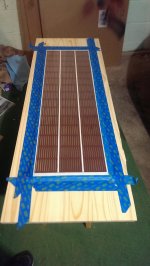
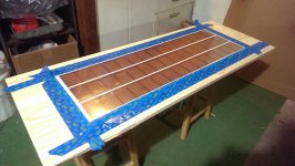
Btw, here are some pics of the stretched diaphragm applied to the stator with 1/16" thick tape. I have already coated it with Licron. Now just waiting 24hr for it to dry.
The PCB is 1/32" thick, including the copper clad. Of course the copper clad is quite thin.
Btw, here are some pics of the stretched diaphragm applied to the stator with 1/16" thick tape. I have already coated it with Licron. Now just waiting 24hr for it to dry.
Attachments
![IMAG0823[1].jpg](/community/data/attachments/436/436423-f2428a5e670b9a26ecd062511f4c61be.jpg)
Each resistor between segments is 220kOhm rated to 500V. Of course both stators have resistors so these effectively double. I have 33 total segments.
I was a bit worried about this at first but the voltage across the resistors is quite low while listening to anything other than sine waves.
I was a bit worried about this at first but the voltage across the resistors is quite low while listening to anything other than sine waves.
It has been a while since I've posted an update. I have been very busy with work and progress has been slow.
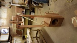
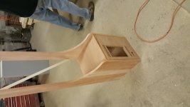
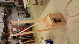
I should have these done in the next few weeks, though. The cabinets are in work (pics attached). They are made of solid mahogany (the side pieces, lots of misc pieces) along with mahogany veneered MDF (the front baffle, rear panel).
I should have these done in the next few weeks, though. The cabinets are in work (pics attached). They are made of solid mahogany (the side pieces, lots of misc pieces) along with mahogany veneered MDF (the front baffle, rear panel).
Attachments
")

Thanks for sharing your progress!
Very professional looking work there.

Thanks!
Actually I just chose a stain for the wood. Some time next week I will stain and clear coat the cabinets, and then mount the components. I will provide lots of pics.
I am planning my next ESL Build - an acoustat based setup with three 9" panels, all flat side by side... with modified Acoustat interfaces.
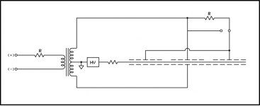
Now to widen the sweet spot - thinking of tying the front stators together, but per Bolsert's diagram, the back stators having a series 50k resistor on both sides...kinda remember this is the way the spectra series panels are set up...
Now to widen the sweet spot - thinking of tying the front stators together, but per Bolsert's diagram, the back stators having a series 50k resistor on both sides...kinda remember this is the way the spectra series panels are set up...
Attachments
thanks john...I had not saw this setup.....
I like the flat panels setup....an run my 3 panels ...with 2 panels running on the nom 121 setup fullrang...then run the outside 1 panel back befor the caps....right off high frec tran secdary.....so that feeds the 1 outside all above what ever the c mod crossover point is....maybe 1k.... then pull the backing off the one outside panel......
Wow.. best topend, sound stage an imageing ever.....the 11 one panel in the pic.....could be setup like your saying......look at that 10meg on the cent tap.....what the hell?.........nice
Attachments
![453423d1418321176-acoustat-answer-man-here-spectra_11_schematic[1][1].gif](/community/data/attachments/452/452539-7d0e0d8c86b3060c46547c35f1a91689.jpg)
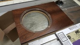
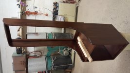
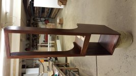
Looking good! Thanks for continuing to share your progress.I am assembling these things to completion this weekend. Here are some pics after finishing the cabinets (before assembly).
- Status
- This old topic is closed. If you want to reopen this topic, contact a moderator using the "Report Post" button.
- Home
- Loudspeakers
- Planars & Exotics
- First time ESL builder