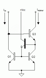
Actually that one is called a swap mirror. I was thinking more like this...
Degeneration feedback resistors for the emitters of Q1 & 2 is needed unless you use matched array devices.
Attachments
So I'm trying to get a grip on the math involved, using mostly Bob Cordells "Designing Audio Power Amplifiers" as a guide.
R7 and R9 will often be selected to drop about 100mV to help with transistor matching(Vbe drops), not very critical value.
I'm running R5 at 240 Ohm, which gives me a tail current of about 2.7mA(0.65/R5), this is divided in two giving us 1.35mA. Ohms law gives us 135mV(1.35mA*100), which is great.
The re of Q7 and Q8 is about 19.2 (26/1.35), which by CBS240s preferences gives us R17/R18 around 40 Ohms, although the book is using 470 Ohms resistors at 1mA tail current. *confused*
OPS input impedance is about betaQ4*betaQ1*zLoad = ~100*~50*8 = 40K.
VAS Input Impedance becomes beta Q6*Q6re = ~100*(26/6.5) = 400.
VAS Gain becomes Zops/Q6re = 40k/(26/6.5) = 10k.
The book becomes somewhat fuzzy on IPS w/CM gain, the formula given is 2*(Zvas/1k), where the 1k is coming from I don't know, but if we take the 1k as a constant we get 2*(400/1000) = 0.8 (wooohooo!).
Open loop gain is then IPS-Gain * VAS-Gain* OPS-Gain = 0.8 * 10k * 0.96 = 7680.
Improving the IPS-Gain would be a first choice, and I want to do that by increasing VAS Input Impedance. If we turn the VAS into a darlington we can get loads more impedance which loads the IPS less.
The book is a little bit fuzzy here, it says the VAS Input Impedance is largely determined by a 470 Ohm resistor between base and VEE, but it gives no further explanation.
If we say the VAS Input Impedance goes to 40k(the figure in the book), IPS-Gain increases to 2*(40k/1k) = 80, very much better(still, the 1k might be bogus, beware!).
VAS-Gain is dependent on OPS-Input-Impedance and is therefore unchanged at 10k, but if we put in a degeneration resistor of 22 ohm, the total re becomes 22+(26/6.5) = 26. This in turn gives us less VAS-Gain(40k/26 = 1538), but promises better linearity.
Open Loop Gain with these changes finally becomes 80*1538*0.96 = 118k an 15times increase. Does this sound better? I have no idea, but I hope to find out!
Do note that I have not implemented a current limiting VAS, making it really easy to damage the circuit if driven hard enough.
Please let me know if my ramblings make any sense, I understand some of it, but I cannot say I got the whole story straight.
-
Kolbjørn
An externally hosted image should be here but it was not working when we last tested it.
Did a little THD simulation comparing the two latest revisions.
No major changes really...
Will have a pcb ready for testing later this evening.
-
Kolbjørn
No major changes really...
Will have a pcb ready for testing later this evening.
An externally hosted image should be here but it was not working when we last tested it.
-
Kolbjørn
Got a pcb finished, populated and working:
Appart from half a dozen accidental solderbridges between tracks, the failing transistors because of the bridges and one busted headset it went very well.
Spent maybe an hour and a half putting it together, the next 5 troubleshooting and testing parts. Thank god for LTSpice, having approximate voltages to check for is very handy.
The headset got busted when I accidently shorted out the amp, it seems headphones does not like railvoltages...
It also seems the amp is a tad susceptible to ripple from the PSU, might need more PSRR or kill some groundloops.
I have learned a few important things from this endeavour,
firstly, I can produce PCBs with 10 mil gap between tracks,
secondly, a 10 mil gap is extremely little when you are soldering,
thirdly, don't short out the amp,
fourthly, I love soldering, fifthly, do not drink lots of coffee before soldering, this leads to shaking which leads to solderbridges and so forth
and lastly I need more PSRR in the amp!
Oh, and it sounds great, now I just need a new pair of headphones
-
Kolbjørn
An externally hosted image should be here but it was not working when we last tested it.
An externally hosted image should be here but it was not working when we last tested it.
An externally hosted image should be here but it was not working when we last tested it.
Appart from half a dozen accidental solderbridges between tracks, the failing transistors because of the bridges and one busted headset it went very well.
Spent maybe an hour and a half putting it together, the next 5 troubleshooting and testing parts. Thank god for LTSpice, having approximate voltages to check for is very handy.
The headset got busted when I accidently shorted out the amp, it seems headphones does not like railvoltages...
It also seems the amp is a tad susceptible to ripple from the PSU, might need more PSRR or kill some groundloops.
I have learned a few important things from this endeavour,
firstly, I can produce PCBs with 10 mil gap between tracks,
secondly, a 10 mil gap is extremely little when you are soldering,
thirdly, don't short out the amp,
fourthly, I love soldering, fifthly, do not drink lots of coffee before soldering, this leads to shaking which leads to solderbridges and so forth
and lastly I need more PSRR in the amp!
Oh, and it sounds great, now I just need a new pair of headphones
-
Kolbjørn
Great job, I'm glad to hear it is working.

I can assure you, you are not the only one who has done this. Sorry to hear about your busted headphones. I always use cheap garbage speakers I rip out of old junk to do initial tests.
10mil gaps between tracks is pretty good for a home-made PCB. I have created my own share of short circuits and blown transistors as the result. It happens to everyone at sometime. Coffee leads to shaky hands and unintentional solder bridges, alcohol consumption simply leads to mistakes. It helps to have a clear mind when doing this kind of stuff. Have you considered a regulated power supply?
Yeh, oooops!The headset got busted when I accidently shorted out the amp, it seems headphones does not like railvoltages...
I can assure you, you are not the only one who has done this.
 Sorry to hear about your busted headphones. I always use cheap garbage speakers I rip out of old junk to do initial tests.
 I have learned a few important things from this endeavour,
firstly, I can produce PCBs with 10 mil gap between tracks,
secondly, a 10 mil gap is extremely little when you are soldering,
thirdly, don't short out the amp,
fourthly, I love soldering, fifthly, do not drink lots of coffee before soldering, this leads to shaking which leads to solderbridges and so forth
and lastly I need more PSRR in the amp!
10mil gaps between tracks is pretty good for a home-made PCB. I have created my own share of short circuits and blown transistors as the result. It happens to everyone at sometime. Coffee leads to shaky hands and unintentional solder bridges, alcohol consumption simply leads to mistakes.
 It helps to have a clear mind when doing this kind of stuff. Have you considered a regulated power supply?
Have you considered a regulated power supply?
For the next evolution of the project I am thinking of regulating the voltage down to about +-9v, that will give me an output of about 100mW at 250 Ohms and 666mW at 32 Ohms.
Next evolution:
An externally hosted image should be here but it was not working when we last tested it.
Changes involve output triple, dual VAS, improved current mirror in LTP, lowered current in LPT(around 1.4mA now), gain adjusted to get maximum output power at around 700-750mV input, high-gain transistors where needed and changed the output transistors to BD139/140.
Frequency response:
An externally hosted image should be here but it was not working when we last tested it.
-
Kolbjørn
Made another prototype headphone amp, this based on the latest schematic:
First impressions is that hooking the bias transistor up thermally to the output-stage is very important! The output-stage bias is running away when hot. Oh well, lesson learned for next project.
Other impressions is that it's not that different from the last one, could be my hearing that's off the mark.
I had both of them hooked up, one on each ear. Very happy with the results.
Actually, I was so happy with the result that I went ahead and made another amp, this one for my sub:
It's basically the same circuit as the headphone-amp, except on the points of supply-voltage, which is +-40v, the double output-transistors(MJL21193/MJL21194) and obviously the transistors that was not up to the voltage.
Notice also the PSU which got stuck at the proto-stage
The amp is working beautifully, plenty of power for my use. Simulated it gives about 80W in 8 Ohms, 150W in 4 Ohms(at ~400mV input), real values will be lower as the powersupply will sag a bit, losses in components and the danger of pcb-tracks melting at high current.
Where do we go from here? What is next, in terms of fidelity? My guess would be dual LTPs, but other than that I'm blank.
-
Kolbjørn
An externally hosted image should be here but it was not working when we last tested it.
First impressions is that hooking the bias transistor up thermally to the output-stage is very important! The output-stage bias is running away when hot. Oh well, lesson learned for next project.
Other impressions is that it's not that different from the last one, could be my hearing that's off the mark.
I had both of them hooked up, one on each ear. Very happy with the results.
Actually, I was so happy with the result that I went ahead and made another amp, this one for my sub:
An externally hosted image should be here but it was not working when we last tested it.
It's basically the same circuit as the headphone-amp, except on the points of supply-voltage, which is +-40v, the double output-transistors(MJL21193/MJL21194) and obviously the transistors that was not up to the voltage.
Notice also the PSU which got stuck at the proto-stage
The amp is working beautifully, plenty of power for my use. Simulated it gives about 80W in 8 Ohms, 150W in 4 Ohms(at ~400mV input), real values will be lower as the powersupply will sag a bit, losses in components and the danger of pcb-tracks melting at high current.
Where do we go from here? What is next, in terms of fidelity? My guess would be dual LTPs, but other than that I'm blank.
-
Kolbjørn
Where do we go from here? What is next, in terms of fidelity? My guess would be dual LTPs, but other than that I'm blank.
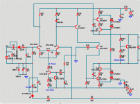
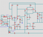
A blameless (your amp) will still sound the same on either an EF2 or a triple. Since you have a working triple , why not try some other topology ? (below 1) and ( 2) may seem simple , but they really sing on a triple.
1 is the luxman - absolutely the best on a triple (ultralow THD)
2 is great for subs and just about any other purpose. The voltage amp's current in both circuits is set by the input stages CCS , about a 1:2 ratio (input stage 3.2ma = VAS 6.5ma.
OS
Attachments
- Status
- This old topic is closed. If you want to reopen this topic, contact a moderator using the "Report Post" button.
- Home
- Amplifiers
- Solid State
- First stumbling steps in Solid State


