I ordered some of these, MF72-200D7 Cantherm | Circuit Protection | DigiKey
They start out at 200 ohm and drop to 11.65 ohm at the rated current of 200ma. I want to stick with the CLC filter so I ordered two 30uf 50 volt caps to run in series.
They start out at 200 ohm and drop to 11.65 ohm at the rated current of 200ma. I want to stick with the CLC filter so I ordered two 30uf 50 volt caps to run in series.
The NTC will reduce the first pulse of charge.
What voltage are you expecting?
Calculate that initial peak current. Is the rectifier able to pass that pulse?
The NTC will rapidly heat up, but probably not to the 12ohms @ rated current (2.3Vdrop).
Then the NTC will cool slightly when the operating current has stabilised and the final resistance will probably be between 20ohms and 40ohms.
Will that matter for your B+?
It will vary slightly as current changes. Will that matter?
Last edited:
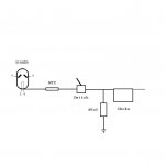
What's the function of the switch?
The transformer winding resistance is important to know, if high enough it should limit inrush current. Since the NTC will settle with a rather high resistance I would just add resistors in series with the rectifier plates if transformer resistance is low.
Maybe put the switch on the HT center tap?
The transformer winding resistance is important to know, if high enough it should limit inrush current. Since the NTC will settle with a rather high resistance I would just add resistors in series with the rectifier plates if transformer resistance is low.
Maybe put the switch on the HT center tap?
Not a valve guy so this might be an old idea, or a bad idea, or an old and bad idea.
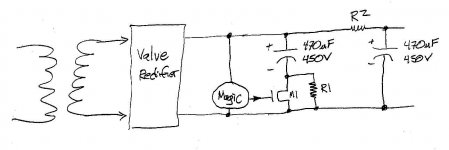
Do you guys ever consider inrush current limiting by active circuitry? Something like the attached works pretty darn well when connecting huge filter capacitors to the output of switching mode power supplies. SMPS cannot tolerate the enormous output current needed to charge big filter capacitors at power-up, so people install active current limiter circuitry to smear out the current waveform and keep its peak well below the SMPS max.
Something like the attached. MOSFET M1 is an 800 volt high power device on a heatsink (IXFP20N85X et al). At startup the Magic gate driver circuit sets M1's gate voltage to just the right magic value that keeps M1's drain current below 100mA (or whatever maximum value the circuit designer has chosen). Eventually the MOSFET's drain falls all the way to zero volts and now the filter capacitor C1 is fully in-circuit with a negligible extra series resistance.
Yes, grab the ipecac, it's a silicon device in your vacuum state worship temple. But maybe it performs a useful and agreeable function?
(R1 is a multi megohm bleeder)
_
Attachments
The purpose of the switch is to allow the tubes to heat up before the B+ is applied. In that way the tubes will be able to conduct from the moment B+ is applied. I think the inrush current is increased because the non conducting tubes act as a brick wall to the power supply. The MFA amps as well as some others use the same arrangement. They put the filaments on a 'Standby Switch.'
Hey All, I was thinking of this. Can anyone foresee any problems? The filaments and bias supply will be on the main power switch.
Hot switching is not a good idea for a couple of reasons: putting that switch on the front panel puts the HV within reach of the end user. It also puts considerable stress on hollow state diodes.
The purpose of the switch is to allow the tubes to heat up before the B+ is applied. In that way the tubes will be able to conduct from the moment B+ is applied.
That's not necessary unless you're using a solid state power supply, and direct coupled stages. With SS diodes, the DC comes up much faster than cathodes can warm up, and that will over volt DC coupled stages. Hollow state diodes take some time to warm up, so you won't have that problem.
Ig your stages aren't DC coupled, then don't worry about it. The only occasion for delay/surge limiting are high current power supplies for high powered audio or RF amps
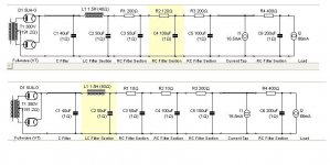
Hey, I've included two screen captures of the power supply. The first is the original. The second was a modification to get more B+ for the front end. I noticed a problem when I made this modification. On startup I heard a 'pop' even before the filaments could warm up. If I stick with the modified power supply I was thinking of substituting the NTC thermistors for R1 and R2 in the power supply. Sound logical?
Attachments
Last edited:
No, I meant in series with the mains transformer primary. It just seems to me (of little knowledge) that's where I'd put a thermistor - not in the B+. Then everything connected to that AC circuit would get a soft start. My guess is you might need a different spec'd part as it would be seeing the draw from everything rather than one DC loop. I dunno, just asking.
If you put the thermistor on the AC primary its like no delay at all.
i do it all the time in my tube amp builds....and why not?
the extra resistance in the primary limits starting currents,
the 5 to 12 ohms cold resistance becomes less than an ohm
as soon as current starts flowing and that NTC heats up....
The other problem is that the thermistor is rated for 200ma. The entire amp at quiescent current will draw about 2.8 amps on the primary side. It wouldn't last very long.
if you know that to be a problem, then you know the solution,
get an NTC of the correct size and worry no more...
Another problem is that PSUDII doesn't allow for the addition of components before the rectifier. Unless you are simply adding the resistance in data for the power transformer? But I'm not sure what effect that would have on the model. Just finished adding the thermistor between the rectifier and the choke/fist cap node. I'll power it up tomorrow night and let you know how it works.
That's only 300W if the primary current is pure sinewave from 115Vac and the transformer is 94% efficient at that loading.
It's a lot less if that 2.8A is a peak value during the pulsing of the primary current to match the pulsing of the secondary current charging up the smoothing capacitance.
It's a lot less if that 2.8A is a peak value during the pulsing of the primary current to match the pulsing of the secondary current charging up the smoothing capacitance.
i have built tube amp on ecl82 tubes. calculated values with PSUD2 program are not corectly calculated,in real world voltages and voltage ripples was different by 20%. so dont believe what this program calculates.
for example 1 cap afer 5u4g 3.3uf and 22uf. in program shows huge voltage drop with 3.3uf. in real life it was 2 volts") in program 25v.
in program 25v.
for example 1 cap afer 5u4g 3.3uf and 22uf. in program shows huge voltage drop with 3.3uf. in real life it was 2 volts
in program 25v.- Status
- This old topic is closed. If you want to reopen this topic, contact a moderator using the "Report Post" button.
- Home
- Amplifiers
- Power Supplies
- First PSU Capacitor