SY, the article was definitely useful: lots of info.
I was reading one of your previous post related to one of my schemas where you wrote:
I didn't get your question and I just changed the design, but you didn't ask me just "Why a balanced output"... you asked "why balance output vs unbalanced input" if I well understand your question now.
I started the design of my pre phono considering the cartridge output as an unbalanced output but that was just my assumption, actually a simplification. So the input of the pre phono has always been designed as an unbalanced input - even because I can understand balance vs unbalance when we talk about output but balance/unbalance input is not so clear in my mind...
For instance I have found a phono from '90s (Siren Song http://www.newworldeconomics.com/archives/2013/040713_files/Morrison%20Siren%20Song%20phono%20pre.pdf) where we have a balanced input.
I'm I missing something important? There could be a possible way to design a good total/partial balanced pre phono? any relevant benefit a part from the balanced output? that is a good point in my case considering the input of the UcD400 (my power amp) is balanced
I was reading one of your previous post related to one of my schemas where you wrote:
Question- why do you have a balanced output but a single-ended input?
I didn't get your question and I just changed the design, but you didn't ask me just "Why a balanced output"... you asked "why balance output vs unbalanced input" if I well understand your question now.
I started the design of my pre phono considering the cartridge output as an unbalanced output but that was just my assumption, actually a simplification. So the input of the pre phono has always been designed as an unbalanced input - even because I can understand balance vs unbalance when we talk about output but balance/unbalance input is not so clear in my mind...
For instance I have found a phono from '90s (Siren Song http://www.newworldeconomics.com/archives/2013/040713_files/Morrison%20Siren%20Song%20phono%20pre.pdf) where we have a balanced input.
I'm I missing something important? There could be a possible way to design a good total/partial balanced pre phono? any relevant benefit a part from the balanced output? that is a good point in my case considering the input of the UcD400 (my power amp) is balanced
The idea is that the output of a phono preamp is high level and low impedance, so noise pickup is much less of an issue for domestic lengths of interconnect. So balanced is fine at the output, but doesn't carry a big advantage unless (like me), the rest of the system is run in balanced mode.
Conventionally, phono inputs are unbalanced. It's QWERTY (I don't know if that's understandable to an Italian, I don't have an Italian keyboard!), that is, it's less than optimal, but because of history, it's what 99.99% of the world does. DIYers have the opportunity (at the expense of extra cost and incompatibility with their friends' systems) of doing things right and running the input balanced- that's where signal levels are low so there's tangible benefit. Now, if this is your first phono stage and you're trying to keep things simple, don't do it this way, save that for an advanced project. My suggestion of that article was to illustrate the differences between balanced and unbalanced and to walk through a detailed design analysis (much in the manner that Morgan does, though admittedly he's a better writer than I am) so that you can see how it's done.
Conventionally, phono inputs are unbalanced. It's QWERTY (I don't know if that's understandable to an Italian, I don't have an Italian keyboard!), that is, it's less than optimal, but because of history, it's what 99.99% of the world does. DIYers have the opportunity (at the expense of extra cost and incompatibility with their friends' systems) of doing things right and running the input balanced- that's where signal levels are low so there's tangible benefit. Now, if this is your first phono stage and you're trying to keep things simple, don't do it this way, save that for an advanced project. My suggestion of that article was to illustrate the differences between balanced and unbalanced and to walk through a detailed design analysis (much in the manner that Morgan does, though admittedly he's a better writer than I am) so that you can see how it's done.
[...] Now, if this is your first phono stage and you're trying to keep things simple, don't do it this way, save that for an advanced project [...]
Ok, I get the point. I keep going with the standard unbalanced input as first experience ("QWERTY" is understandable
 )
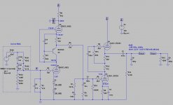
)Ok, I tried to add a common cathode as second stage (based on ECC83, with CSS) but the final gain was 40-41dB.
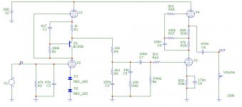
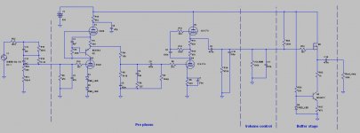
So I reintroduced the mu-follower (based on ECC83 - no CSS here) and also I found (don't remember where) a different way to arrange the RIAA network in order to have less attenuation.
The solution is in attach.
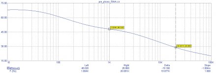
The simulator says I have 48dB @ 1KHz that meets my requirement, the RIAA stage is not so accurate as the previous one @ 20KHz but I think it's acceptable for a first project.
You don't see any buffer stage here because after this pre phono I'm going to add the input selector (CD, aux...), the volume control and than the buffer stage of the pre amp (with a bit of gain, let's say 2-4x)... and the buffer stage will be another challenge
Any comment/suggestion?
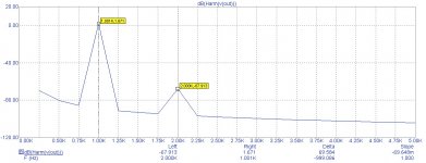
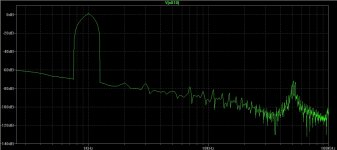
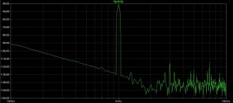
PS: I'm adding the freq response @ 1KHz. Not sure if this is a good starting point to evaluate the THD but at least it gives an indication about the second harmonic: close to -70dB.
So I reintroduced the mu-follower (based on ECC83 - no CSS here) and also I found (don't remember where) a different way to arrange the RIAA network in order to have less attenuation.
The solution is in attach.
The simulator says I have 48dB @ 1KHz that meets my requirement, the RIAA stage is not so accurate as the previous one @ 20KHz but I think it's acceptable for a first project.
You don't see any buffer stage here because after this pre phono I'm going to add the input selector (CD, aux...), the volume control and than the buffer stage of the pre amp (with a bit of gain, let's say 2-4x)... and the buffer stage will be another challenge
Any comment/suggestion?
PS: I'm adding the freq response @ 1KHz. Not sure if this is a good starting point to evaluate the THD but at least it gives an indication about the second harmonic: close to -70dB.
Attachments
Are you sure, that this type of first stage working properly?
Two series red LED represent about 2.9-3V bias.
12AX7 -3V curve: at 250V plate Ia is about 180-200uA;
This is the mostly crooked part of the curve.
Simulated (LTSpice) circuit gain is about 42.5dB (at 1kHz), but sweep has 10dB hump at 7Hz!
IMHO mu-follower is better option.
Two series red LED represent about 2.9-3V bias.
12AX7 -3V curve: at 250V plate Ia is about 180-200uA;
This is the mostly crooked part of the curve.
Simulated (LTSpice) circuit gain is about 42.5dB (at 1kHz), but sweep has 10dB hump at 7Hz!
IMHO mu-follower is better option.
Sorry for the misunderstanding: the first is based on ECC88. Only the second stage is based on ECC83.
We discussed the first stage few post before: due to a problem with my pc I lost the file of the circuit and I redraw it last night without specifying the tubes. So X1-X2 = ECC88 and X3-X4 = ECC83.
Really appreciate your feedback with this new info.
We discussed the first stage few post before: due to a problem with my pc I lost the file of the circuit and I redraw it last night without specifying the tubes. So X1-X2 = ECC88 and X3-X4 = ECC83.
Really appreciate your feedback with this new info.

Well, that's another story.
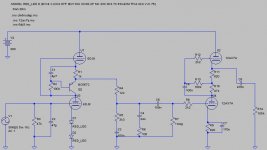
In my simulation I readjusted emitter resistor to balancing upper tube bias equal to the LEDs voltage (lower tube bias). Upper tube Vac was too large, R9 dropping resistor is needed.
12k (RIAA first resistor) was a little bit, 18k is better (trim it to adjust lower hump of transfer curve). RIAA serial R-C tags also adjustable with resistors.
Gain about 49dB, distortion is good (about -68dB second harmonic), transfer curve is smooth.
Attachments
Last edited:
It seems we have a winner 
I have a question, just to expose my ignorance... again. Considering the anode voltage, I guess I have to bias the heater of the upper tubes. Now, I'm a bit confused about how to split the tubes considering we have right/left channel.
What's the solution here for the input stage (the same for the output), using two ECC88, one biased (upper tube) and the other one not biased (lower tube) and using one half for the right channel and the other half for the left channel? I mean: the same physical tube for the two channels?! Is there a way to have a sort of dual mono implementation?
Yes.What's the solution here for the input stage (the same for the output), using two ECC88, one biased (upper tube) and the other one not biased (lower tube) and using one half for the right channel and the other half for the left channel?
E88CC cathode-heater limit is 150V (if cathode positive). I almost exclusively use DC heating in tube phono, and 30-40V positive voltage over the cathode potential.
This schematic upper tube is near the limit (135V), with increased potential this voltage will be greater than 150V.
I rather use one tube for the same positions.
Ok, so I assume that using the same tube for the two channels is a safe practise.
As a newbie I thought there could be some kind of interference or degradation in channel separation using the same physical tube for both the channels (half for right and the other half for left).
As a newbie I thought there could be some kind of interference or degradation in channel separation using the same physical tube for both the channels (half for right and the other half for left).
Phono cartridge channel separation is 20...45dB (at 1kHz). In the upper side the price about a few thousand dollars!
Dual triode crosstalk example:
http://www.diyaudio.com/forums/tubes-valves/260477-crosstalk-between-triodes-dual-triode-tubes.html
E88CC -70dB at 1 kHz, -54dB at 10 kHz, -47 dB at 20 kHz.
If you use russian (NOS soviet is better) 6N23P triode, it has groundable shield between triodes at pin 9.
Dual triode crosstalk example:
http://www.diyaudio.com/forums/tubes-valves/260477-crosstalk-between-triodes-dual-triode-tubes.html
E88CC -70dB at 1 kHz, -54dB at 10 kHz, -47 dB at 20 kHz.
If you use russian (NOS soviet is better) 6N23P triode, it has groundable shield between triodes at pin 9.
For buffering the output, you might consider MOSFETs. Morgan and I did some measurements on source followers vs cathode followers under different loading, and the source follower was better every time. You'd want low Crss.
Studying the output stage of the preamp, I'm considering SY's advice of using source follower (MOSFET).
Now I have few questions:
1) I've found lot's of different schemas and implementations, everyone using a different NMOS. Is there any advice about the model I should consider?
2) Regarding the Vdd, should I go for a "high voltage" MOSFET (+300V) or a "more standard" (+30V) MOSFET is a better choice?
3) considering the source follower has a gain of 1 and I need to get another 2x-5x from the output stage (that is actually a line stage in my case), I'm thinking to use a common cathode before the MOSFET. I guess I can go with another ECC88 and find a way to keep the gain low and controlled by a pot - any side effect?
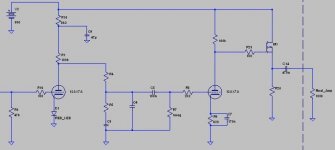
Just to share a possible complete design.
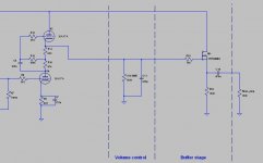
Introduced the MOSFET as source follower, I just need an advice about the current I'm supposed to manage here (2.5mA with the values you can see in the attached schema) and if possible a good working point for the MOSFET - I made some test but it seems the final result is not so impacted.
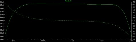
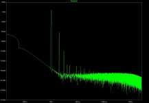
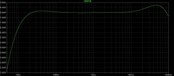
Gain is pretty linear from 15Hz to 100kHz and the distortion seems to be fine (-70dB), now the third harmonic is the one to consider... I guess this is a side effect of the solid state part of the circuit.
Volume control is here a fixed resistor just to make simulation easy.
Final amp input impedence is 100KOhm (UcD400 module from Hypex).
Introduced the MOSFET as source follower, I just need an advice about the current I'm supposed to manage here (2.5mA with the values you can see in the attached schema) and if possible a good working point for the MOSFET - I made some test but it seems the final result is not so impacted.
Gain is pretty linear from 15Hz to 100kHz and the distortion seems to be fine (-70dB), now the third harmonic is the one to consider... I guess this is a side effect of the solid state part of the circuit.
Volume control is here a fixed resistor just to make simulation easy.
Final amp input impedence is 100KOhm (UcD400 module from Hypex).
Attachments
Directly couple...
Ok, done. I have 133V biasing the gate and 127.5V on the source now.
I guess I should add a drain resistor to maintain Vds between 10-20V at least looking at the diagrams coming with the datasheet of the suggested MOSFET
Attachments
Ok, done. I have 133V biasing the gate and 127.5V on the source now.
You can't put DC on the volume control, from either direction.
Normally the volume control would be after the buffer and the output coupling capacitor.
Last edited:
This design is way overcomplicated, especially for something you're going to have to test and debug as a newbie. Why the obsession with mu followers? A single 12AX7 could do the same job at a fraction of the cost. The significant difference would be a bit more Miller capacitance at the input and a lot less self flagellation. Not far off what you started with at the begnning of this thread (which you could have built by now...)
Attachments
Last edited:
- Status
- This old topic is closed. If you want to reopen this topic, contact a moderator using the "Report Post" button.
- Home
- Source & Line
- Analogue Source
- First pre phono design [newbie]