> Getting a PP and a SE .... exercise to get a student his masters degree?
I have suspected that CBS accidentally wired-up a batch of ceramic needles wrong-phase, and invented this matrix amp to sell the stuff.
However it gets the Bass (invariably center-mono those days) into a P-P amplifier and transformer for better boom (per dollar!). The L-R signal was less important since the majority of records had poor "stereo" and the majority of users didn't have a clue. And these were distinctly LOW-price "Stereo!" sets. If the train drove from one speaker to the other, WOW! If the piano and guitar were on different sides, golly. But just as often one speaker was in the living room and the other in the den.
I had a {censored} two-60FX5 true-stereo cardboard set which actually imaged pretty good when carefully set up. But that was long after the CBS Matrix.
Here's what I'd do.
For a first time builder, a single ended amp made from a 12AX7 and EL84 per channel will offer a good challenge. So find a schematic that offers that topology and build that. Drive it with an outboard preamp or a digital frontend for now. Just get the amp working well first, being driven from some sort of line level source. Realistically you'd be looking at 3.5 to 4 watts per channel with that topology.
Then build a line level preamp. You might have better success with a separate chassis just for the preamp, but if you plan ahead you could come back and add the preamp stage to the power amp chassis. It will be harder to get it quiet though, if preamp is on the same chassis as power amp, but can be done. Test it with a digital front end same as before. If you elect to put the preamp on the amp chassis, you may not find a pre-engineered and tested schematic for just what you need, but if you state that is your desired direction, people here on the forum can help you piece together a design that will work well.
After amp and preamp are working well, then purchase a cheap solid state phono preamp for now and enjoy your system for a while. When you feel up to the challenge, tackle building a phono preamp. It is a much more difficult task to build a phono preamp than building either the amp or preamp (difficulty arises in making it quiet and getting that inverse RIAA curve correct). You need to develop skills first before tackling a DIY phono preamp.
My opinion from someone who was once in your position.
I have also read that el34 and 84 can be exchanged. Only difference is 34 has more power and different tone
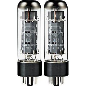
Oh good grief! No, they cannot be exchanged - where ever did you read this? Here, let's take a quick comparative look at the two types..
This is a pair of EL34 / 6CA7 - these are good for 35-40W / pair in P-P service. Notice they are octal-based (8-pin) tubes:
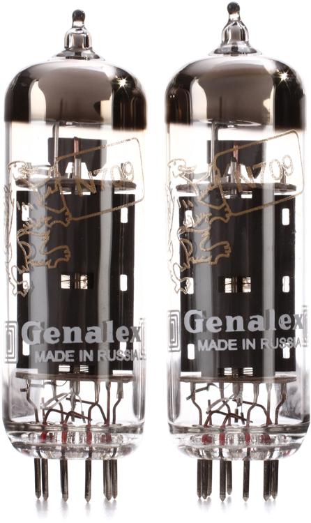
Next, a pair of EL84 / 6BQ5 - good for 15-17W / pair in P-P service. Notice they are 9-pin miniature based:
For a comparison of relative sizes:
An externally hosted image should be here but it was not working when we last tested it.
From Left to Right: EL84 / 6BQ5, 6V6, EL34 / 6CA7, 6L6GC and GE 6550(?)
Last edited:
As others have explained that console was 'unusual' - weird almost - and not at all typical of tube stereo amps. I've looked at many many tube amp schematics, built a bunch, and I'd never seen anything like your console. So, I agree with others who have said that it's probably not the best 'starting point' for your tube amp 'journey'.please forgive my ignorance, there is nothing in the schematic i have indicating both PP and SE transformers in this console. I was under the impression that PP required twice the number of tubes per channel.
However, if you insist on using the output transformers from the console, you will pretty well be compelled to rebuild the original design (with its flaws).
If you look at the two OTs in the schematic, notice how one has 3 primary wires (typical of some PP OTs) and the other has 2 primary wires (simple SE OT). For all 'standard' stereo tube amps, the two OTs are as identical as possible, not different as in this example.
You are correct: an EL84 PP stereo amp would have 2 pairs of output tubes (at least).
You need a pair of SE output transformers for your project if you want to use one EL84 per channel.
A pair of PP output transformers will work with two EL84 tubes per channel.
Generally, SE transformers are more expensive than PP transformers, though you can get SE OTs from salvage or cheap ones designed for guitar amplifiers if you are on a budget.
The amp as a whole was a 2 channel stereo amp (no matter the special configuration).
I did not say it was a Push Pull amp; it merely used 2 SE channels driving a Push Pull transformer; and a SE transformer that was driven by the sum of varying currents passed through from B+ to the center tapped "PP" transformer. The matrix connection of the SE secondary and PP secondary 'did the math addition and subtraction' to produce the L and R channel outputs.
If the cartridge was out of phase (and many vinyl grooves have bass in phase), then the bass in L and R to the 2 channel input would be in opposite phase. So, there would be no change in the B+ current from the bass signal in the Center Tap of the "PP" transformer. That would mean there was no output from the SE transformer, and the matrix idea would fall apart (the math does not work in that case).
That also means if any vinyl recording had bass out of phase, and a cartridge with correct phase, there would be no bass output in the L and R channels (one case where the matrix math falls apart).
Perhaps one PP transformer plus one SE transformer was a little less expensive than using 2 SE transformers, and the manufacturer saved a little expense by using this combination (less laminations, less wire, and less weight in the PP transformer). Was that the reason for the strange topology, who knows.
I remember when this topology was written up in an electronic magazine. But that was about it. The manufacture production of this kind of topology stopped early, for good reason.
And it probably had some technicians heads spinning if they ever had to repair the amp.
With the original parts it pretty well has to be 2 SE channels, but of course that means at least 1 extra SE transformer, or much better yet 2 matched SE transformers.
Finding another identical amp chassis and transformers is not likely (but then you could make 2 Push Pull mono block amps out of 2 chassis).
Personally, I vote for more classical circuits.
- Status
- This old topic is closed. If you want to reopen this topic, contact a moderator using the "Report Post" button.