If you haven't got one already then I suggest you set up a light bulb tester http://www.diyaudio.com/forums/power-supplies/167579-light-bulb-tester.html It should minimise the damage when you power up should there be any problems.
Double check all of your Electrolytic caps for correct polarity before powering up as well, and to be on the safe side, wear some eye protection as well")
Tony.
Double check all of your Electrolytic caps for correct polarity before powering up as well, and to be on the safe side, wear some eye protection as well
Tony.
Last question hopefully. I have made changes in caps thanks to peoples advice but the psu is still like the link in my first post: two bridges, with two separate rails one with +PGND and the other with -PGND at the end and what looks like a connector between the +PGND and -PGND. What I am confused about is how to wire it. Do I connect +PGND, -PGND, the purple wire of the transformer (link to is also in first post), and the chassis all directly to earth (3rd round prong in the US)?
The purple wire can go directly to chassis or earth. (So do the two PGNDs, but see below for those.)
It matters exactly how the PSU grounds are routed and exactly where you connect the ground of the smoothing capacitors and the star ground to safety earth. (Also note that earthing is only required for safety.)
Your "star ground" point should be basically at the OUTPUT of the power supply, near where the +PGND to -PGND connection is shown, in your diagram, which should be very near the grounds of the last large smoothing caps, i.e. farthest from the rectifiers. That way, your amplifier ground returns won't share the same conductor as the charging pulses that flow in the loop(s) between the caps and rectifiers.
You could use a bolt that comes up through the bottom of the chassis, for your star ground, there (paint removed from chassis, under nut!), and use ring terminals to connect all of the different ground wires to the bolt (amp signal input grounds, amp power grounds, amp output or speaker grounds).
You could optionally have a second bolt (isolated from chassis), with a "safety disconnect network" connected between the bolts, and use the second bolt as the star ground.
NOTE that all safety earth connections must be bolted or welded, not soldered, since solder might melt and disconnect the safety earth during a fault condition.
The smoothing caps' connections to the rectifiers should be kept short. And, most-importantly, the V and PGND conductors should stay very close to each other, everywhere, there. If they are wires, then they should be tightly twisted together (about 4 turns per inch should be enough), everywhere possible (i.e. right up to each cap and diode). The conductors from the transformer to the rectifiers should be treated the same way, as should the AC input conductors. Otherwise, they would make good transmitting antennas for hum.
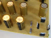
FIRST, remove the 0.1 uF capacitors. They can't do any good at all, that far from the point of load, and could induce resonances, especially if they are low-loss types, like film, or ceramics other than X7R.
And those snubber networks can't do much good, where they are, and probably won't work well at all, anyway, unless the resistor values are tuned to the characteristic impedance of whatever LC network needs to be snubbed (which will probably be the transformer leakage inductance and the diodes' capacitance at turn off, plus maybe a few other strays). Most likely, any snubber would work much better across the transformer secondary's connection to the rectifier bridge, unless you want one across each diode.
If you have an oscilloscope, you can optimize the snubber resistances, after everything else is assembled: http://www.diyaudio.com/forums/powe...lm-caps-electrolytic-caps-30.html#post2828689
You do have at least a fuse for the AC, right? And a switch? Make sure that the two AC Mains wires stay close together, everywhere. Just because only one "needs" to go to a switch does not change that. Run them both, there, tightly twisted all the way, and all the way back, with one hugging the switch as it goes around it. Same for fuse wiring.
Last edited:
1.And, most-importantly, the V and PGND conductors should stay very close to each other, everywhere, there. If they are wires, then they should be tightly twisted together (about 4 turns per inch should be enough), everywhere possible (i.e. right up to each cap and diode).
2.And those snubber networks can't do much good, where they are, and probably won't work well at all, anyway
3.You do have at least a fuse for the AC, right?
4. And a switch?
1. Im using 10 caps per rail so there should be twists between all the caps? I'll post a pic tomorrow if I can of the rail I already put together.
2. Yeah so far I only have the 2 bridges, then the bleed resistors, then the 20x2200uf caps. Ill have more caps close to the LM3886 as each chip will have its own case and the psu will also have its own case. Trying to keep it simple how important are subber networks can they wait till later?
3. I currently don't have a fuse(s) but i will get one for sure, i was going to wait and see what kind of current it draws before deciding on the fuse rating or is that a bad idea?
4. As for the switch I don't plan on putting one in at the moment the one on the surge protector works fine
no volume pot or any switches or knobs lol. I just want a basic version for now and work from there7. the two rails of caps
8. close up of bridge and bleeders
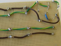
9. brown is ground green/yellow is positive blue is negative. The two grounds will end up together in the center when i finish the other rail, each rail does a 180 half way through
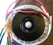
10. transformer
11. power cord it's nice to know what your unplugging and plugging in for once
8. close up of bridge and bleeders
9. brown is ground green/yellow is positive blue is negative. The two grounds will end up together in the center when i finish the other rail, each rail does a 180 half way through
10. transformer
11. power cord it's nice to know what your unplugging and plugging in for once
Attachments
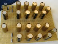
Hi, I'm a little concerned that your caps are mirrored, but I cant tell 100% from your underside how they are wired.
The caps on the negatuve rail should have the +ve of the cap on the 0V line and the negative of the cap on the negative rail. If your zero volts is down the middle of the board, I would think that your caps should all be the same orientation. But it depends on how you have them wired up underneath
Tony.
In the picture they were mirrored but I noticed the same thing right before I started the other rail thankfullyHi, I'm a little concerned that your caps are mirrored
Tony.
T
1 - NOTE that all safety earth connections must be bolted or welded, not soldered, since solder might melt and disconnect the safety earth during a fault condition.
2- FIRST, remove the 0.1 uF capacitors. They can't do any good at all, that far from the point of load, and could induce resonances, especially if they are low-loss types, like film, or ceramics other than X7R.
3- You do have at least a fuse for the AC, right? And a switch?
Gootee - excellent suggestions. may I humbly comment on a few of them?
1 - perhaps you mean brazing, and not welding per se? Plating critical contacts with silver or gold is not such a bad idea.
2 - remove the 0.1 caps only because they are far.... otherwise a good idea
3 - the power switch ought to be double pole [cut both hot wires']
1. Im using 10 caps per rail so there should be twists between all the caps? I'll post a pic tomorrow if I can of the rail I already put together.
2. Yeah so far I only have the 2 bridges, then the bleed resistors, then the 20x2200uf caps. Ill have more caps close to the LM3886 as each chip will have its own case and the psu will also have its own case. Trying to keep it simple how important are subber networks can they wait till later?
3. I currently don't have a fuse(s) but i will get one for sure, i was going to wait and see what kind of current it draws before deciding on the fuse rating or is that a bad idea?
4. As for the switch I don't plan on putting one in at the moment the one on the surge protector works fine
You don't HAVE to twist between each cap. but if you don't, then you should at least tie the wires right against each other, as much as possible.
The snubbers can certainly wait.
Some truly great advice especially if your powering it up before you have got your fuses or your a first timer like me. I say this because after completing the psu with no problems it was time to connect one of the channels. When i did this and turned it on some loud nasty crackling came from the crappy test speakers I had rigged up and the light was lit dimly so i quickly turned it off. Turns out I had forgot about the grn pin on the lm3886 and left it unconnected to anything. After fixing this everything sounds great, no hums or buzzes. Not sure what would have gone down w/o the light bulb tester, it wasn't a short but the current limiting still may have saved the day.I suggest you set up a light bulb tester... It should minimise the damage when you power up should there be any problems.
Tony.
- Status
- This old topic is closed. If you want to reopen this topic, contact a moderator using the "Report Post" button.
- Home
- Amplifiers
- Power Supplies
- First Build (Stereo LM3886) in need of psu advice