
Ahhh, much easier ")
You see the signal from the center of the RCA jack goes to the capacitor C1, and then to the potentiometer? Basically you have to connect that point to pin #2 of V1a. Start at pin #2 of V1a, and then trace the circuit back to the potentiometer mounting pads. Then just jumper these two traces together with a short piece of wire. It can even be buss wire or the cut off part of a capacitor or resistor you already used.
Glenn
BTW: Your chassis looks nice! Are you going to paint it or polish it?
I would do mine the same way. Much nicer than the pine board
thanks again! so i dont need the resistor at all??? thats good to know... ill take a pic of the PCB to make sure i get it right.
as for the chassis...... i will be using wood are the edges and polishing the top.... the wood will be beveled on the top and bottom and tapered inward around the power switch....
as for the chassis...... i will be using wood are the edges and polishing the top.... the wood will be beveled on the top and bottom and tapered inward around the power switch....
jdbrocious said:thanks again! so i dont need the resistor at all??? thats good to know... ill take a pic of the PCB to make sure i get it right.
I'm not sure why you would need the resistor. Unless it's to set the volume to a fixed level other than "full". If it's too loud, you may have to insert the resistor where I told you to use a piece of wire. How was this resistor value arrived at? The only thing I can think of is that this value sets the volume of the amp so that it's not near it's distortion level running at full volume.
You may want to try it both ways to see which you prefer.
Glenn
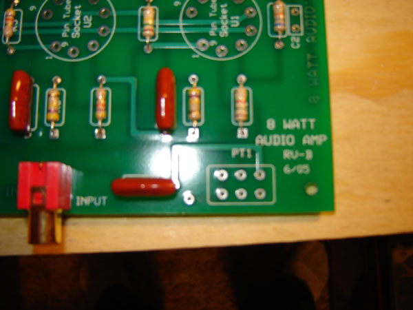
I can see the silkscreened circle labeled "Pin tube socket V1" right behind the volume pot area. See the "1" and "9" labelling the pins of the tube in the circle? Pin #2 is the second pin around the circle starting from the "1" label (makes sense right?). I can see the trace leading from this pin to the volume potentiometer mount on the opposite side of the board. That is the other pad that the pad from the capacitor should be tied to.
alexistheo-
Can you please elaborate on the resistor to ground for the grid?
Is this what you mean?
Glenn
alexistheo-
Can you please elaborate on the resistor to ground for the grid?
Is this what you mean?
Glenn
Attachments
Ok, we're making progress here but I need more information.
Look at this picture, and tell us what pad the trace I've pointed to on the BACK side of the board goes to.
Glenn
Look at this picture, and tell us what pad the trace I've pointed to on the BACK side of the board goes to.
Glenn
An externally hosted image should be here but it was not working when we last tested it.
the pad to the left of the one circled leads to the #2 pin.... so i would need to run a jumper from this pot to the #2 pin correct??? or do i place a resistor in there??
the reason i was confused from the beginning.....the schematic shows U1b and U2b to be the tube sockets i think.....
either way, i guess the jumper has to goto the #2 pin on the number 1 tube socket
the reason i was confused from the beginning.....the schematic shows U1b and U2b to be the tube sockets i think.....
either way, i guess the jumper has to goto the #2 pin on the number 1 tube socket


jdbrocious said:the pad to the left of the one circled leads to the #2 pin.... so i would need to run a jumper from this pot to the #2 pin correct??? or do i place a resistor in there??
the reason i was confused from the beginning.....the schematic shows U1b and U2b to be the tube sockets i think.....
either way, i guess the jumper has to goto the #2 pin on the number 1 tube socket
Yes, that is right the jumper goes there, but you also need to connect the resistor from the junction of these 2 pads to ground. We still need to know what pad connects to ground on the back side. This pad can be located because it will connect to the outside of the RCA input jack. Just solder the resistor to this ground pad on the top side of the board, and connect the other end to the jumper.
So looking at the picture, the jumper goes between the upper right two pads, then the resistor will go to another pad, and then to the jumper. You can also solder on the back side of the board if the board is too close to the chassis on the top.
V1 and V2 are the tube sockets. V1a just refers to half of the tube
, V1b is just the other side. They both are within the same tube though.
Glenn
ok, i think im confused here....... but here is a picture of what i think i should be doing

i dont quite understand why im running a jumper to the #2 pin on the tube.... the PCB shows a connection between these 2 points already... sorry for the rediculous questions, but im learning....
try not to laugh at the soldering job,.... it was my first time
and i had to put the c1 capacitor on the other side of the PCB to fit the power switch
jdbrocious said:i dont quite understand why im running a jumper to the #2 pin on the tube.... the PCB shows a connection between these 2 points already... sorry for the rediculous questions, but im learning....
and i had to put the c1 capacitor on the other side of the PCB to fit the power switch
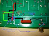
You don't need a jumper all the way back to pin #2 on the tube. There is already a trace there on the board as you can see. Just jumper the 2 upper left-hand pads as shown. This connects the input signal coming from the capacitor directly to pin #2 on the tube. Now you need to add that resistor from this connection to ground. I can see that gound buss as it connects to the outside of the RCA input jack. Solder the resistor vertically into the upper right-hand pad as shown. Then bend the lead over and solder it to the new jumper you just added.
See the picture.
You're almost done!
Glenn
Attachments
No problem, everyone has to learn.
Please post pictures when you are finished.
I'd like to know how this sounds as I'm looking to buy one for my 13 year old Nephew for Christmas. I figure it would be a good learning experience for him.
I see they also make a stereo version, so I may look at getting that instead.
Glenn
Please post pictures when you are finished.
I'd like to know how this sounds as I'm looking to buy one for my 13 year old Nephew for Christmas. I figure it would be a good learning experience for him.
I see they also make a stereo version, so I may look at getting that instead.
Glenn
jdbrocious said:[/B]
ok i have it soldered into place.... look right??
So yes I am still working on this project (3 years off and on)
. anyway, its all together and works but it has very little volume. At half volume on my preamp there is distortion, at full volume it is nothing but distortion. Could that 470k resistor be too much??At about 1/4 volume on the preamp there is little distortion, but I can also barely hear anything at all.
any suggestions?
- Status
- This old topic is closed. If you want to reopen this topic, contact a moderator using the "Report Post" button.
- Home
- Amplifiers
- Tubes / Valves
- first amp build... wiring questions