OK, once that is done, I would tidy up the wiring. I will take a guess and suggest that you did not really plan the layout before your enthusiasm got the better of you and you started just wiring her up! ") I have been there and done that, and the results were not impressive - from a performance point of view. The simplest way of doing the planning is to use a 1:1 mockup on paper. Settle on your layout of the tubes, transformers and switches. Print them in pen on your paper chassis. Then use pencil to place the components and wires taking note of the ground return currents, the signal runs and the high voltage runs. This way you can edit with an eraser. Keep heater wiring tightly twisted and ideally tucked in to the corners. Keep signal wire away from high voltages and currents. Use a star or a bus grounding scheme (or a combination of both). Keep high current earth returns (power supply capacitor grounds, grounds from power tubes) away from the sensitive input tube ground returns.
I have been there and done that, and the results were not impressive - from a performance point of view. The simplest way of doing the planning is to use a 1:1 mockup on paper. Settle on your layout of the tubes, transformers and switches. Print them in pen on your paper chassis. Then use pencil to place the components and wires taking note of the ground return currents, the signal runs and the high voltage runs. This way you can edit with an eraser. Keep heater wiring tightly twisted and ideally tucked in to the corners. Keep signal wire away from high voltages and currents. Use a star or a bus grounding scheme (or a combination of both). Keep high current earth returns (power supply capacitor grounds, grounds from power tubes) away from the sensitive input tube ground returns.
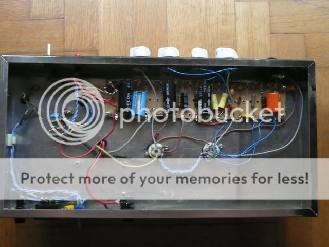
For a hint on layout, look at something like the AX84 site. Find the parts of the schematic that are similar to yours, and lay them out the same. See here http://www.ax84.com/static/p1/AX84_P1_091125.pdf You have put in some nice tag boards, but have failed to use them. Logical neat layout will make trouble shooting and parts replacement MUCH easier.
If you cannot mount your power supply capacitors on the tag boards (radial v axial), then make sure you star ground is right AT the second power supply cap ground. I note that your third and fourth decoupling capacitors for the input tubes are not star grounded. They have the grounds tied together and that junction taken to the star. Not sure if it is causing any problems, but the little things do add up.
Have not gone through the entire wiring to find further issues, too tired, very late here!
I have only built one guitar amp, unashamedly taken directly from AX84 site using their suggested layout. Very easy to troubleshoot...
Here is one I prepared earlier ...
I have been there and done that, and the results were not impressive - from a performance point of view. The simplest way of doing the planning is to use a 1:1 mockup on paper. Settle on your layout of the tubes, transformers and switches. Print them in pen on your paper chassis. Then use pencil to place the components and wires taking note of the ground return currents, the signal runs and the high voltage runs. This way you can edit with an eraser. Keep heater wiring tightly twisted and ideally tucked in to the corners. Keep signal wire away from high voltages and currents. Use a star or a bus grounding scheme (or a combination of both). Keep high current earth returns (power supply capacitor grounds, grounds from power tubes) away from the sensitive input tube ground returns.For a hint on layout, look at something like the AX84 site. Find the parts of the schematic that are similar to yours, and lay them out the same. See here http://www.ax84.com/static/p1/AX84_P1_091125.pdf You have put in some nice tag boards, but have failed to use them. Logical neat layout will make trouble shooting and parts replacement MUCH easier.
If you cannot mount your power supply capacitors on the tag boards (radial v axial), then make sure you star ground is right AT the second power supply cap ground. I note that your third and fourth decoupling capacitors for the input tubes are not star grounded. They have the grounds tied together and that junction taken to the star. Not sure if it is causing any problems, but the little things do add up.
Have not gone through the entire wiring to find further issues, too tired, very late here!
I have only built one guitar amp, unashamedly taken directly from AX84 site using their suggested layout. Very easy to troubleshoot...
Here is one I prepared earlier
...An externally hosted image should be here but it was not working when we last tested it.
Last edited:
Wow that is a great build!
I'm not sure if I have the energy to rebuild this amp completely, but I will do as previously suggested. I do not plan on rewiring the whole thing unless the sound is absolutely terrible and the 60Hz hum is overwhelming.
My next amp will be an AX84, probably the hi-octane. I like to have the capability to have a lot of distortion without using a pedal.
I noticed that the wire I was using is EXTREMELY rigid and hard to work with. Where do you get your 18-gauge wire?
I use regular solid core household power cord wire for the heaters of octal sockets. I normally get 10 feet or so of two and twist the two wires in my cordless drill held by vise at other end. Rest of internal wiring is Teflon coated multi strand I purchased on eBay. The thicker stuff is about 20 guage and used for the higher current runs, the thinner stuff is 22 guage and ok for the signal and low current stuff, however it is more fragile and a little more difficult to work with. 20 guage solid core is probably ok for heaters on 9 pin sockets. The advantage of Teflon coated is that you can touch it with your iron and not melt it.
Honestly, while waiting for yourparts, I would go through the mental exercise of planning out the wiring and component layout properly. If you had done that in the first place you would have made it much easier to trouble shoot for both yourself and anybody trying to assist you.
For me the biggest PITA job is the chassis. You have already done this, the re-wiring is easy, especially if you have a plan to work to
That ground connection....
Dosilegecko: Furthering what Chrish said above, it appears that your chassis is steel, and steel does not solder well. It may be sticking for now, but it won't last long.
That's the most important connection in the amp, especially since it's a guitar amp, your life could depend on it. Use a #8 or #10 screw, a ring lug, and star lockwashers between the ring lug and the chassis, and the ring lug and the nut. Over time, oxidation/corrosion builds up, and the star lock washers bite into the mating metal in multiple places assuring a good ground that lasts a long time.
Fusing the mains hot wire is also important since fusing the neutral leaves the amp live/hot, and potentially ungrounded when the neutral side fuse blows. Also make sure that you are switching the mains hot or both mains and neutral (DP switch), and not switching the mains neutral.
Last edited:
The new build
So......Is that your name scratched onto the turret board? David?
You could have cut that board in half instead of "breaking" it in half...Oh well.
When we create things sometimes enthusiasm gets the best of us!
It is a great build...a few things to iron out yeah...but nice never the less!
When one talks about 'Area' for grounding I'm refering to spreading out the surface area as your grounds all converge.
Ever wonder why car "jumper cables" have these nasty serrated teeth on them?
It's to get a good surface area by biting into the lead terminals on a car battery.......same thing for the grounds.
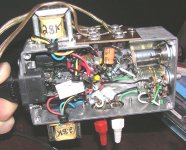
Here's a pix of a truly bad wiring of an amp......too small a chassis & sloppy soldering........my apologies to its originator/owner. I just have the image on tap to remind myself of what not to do.
_________________________________________________________Rick....
So......Is that your name scratched onto the turret board? David?
You could have cut that board in half instead of "breaking" it in half...Oh well.
When we create things sometimes enthusiasm gets the best of us!
It is a great build...a few things to iron out yeah...but nice never the less!
When one talks about 'Area' for grounding I'm refering to spreading out the surface area as your grounds all converge.
Ever wonder why car "jumper cables" have these nasty serrated teeth on them?
It's to get a good surface area by biting into the lead terminals on a car battery.......same thing for the grounds.
Here's a pix of a truly bad wiring of an amp......too small a chassis & sloppy soldering........my apologies to its originator/owner. I just have the image on tap to remind myself of what not to do.
_________________________________________________________Rick....
Attachments
Ya that's my name haha.
I did cut it in half, but not the way I should have!
I tried to use my dremel tool, but the little blades were already in rough shape and broke, so I used a drill, drilled many many little holes, and then slowly cut. That's why it's a sloppy edge.
Does anyone know if it is a bad idea to elevate the heater supply from the 2nd filter cap rather than the first?
Am I looking at the wrong schematic?....The "Mini-cat"??
I don't see any elevated heaters....Your 'A' goes to the anode of the pentode thru the OPT, the 'B' runs the "bias" on the screen grid.then the C & D on down the line.
Elevating heaters are used to compensate for elevated Cathodes as there is a limit voltage for heater to cathode.......its' in the specs for the chosen tube...I forget the designation(Abbreviation).
Blowing thru these limits reek all sorts of havoc..........ask George, he's probably "tested" these limits.
___________________________________________________Rick.........
SO! I put in the new tube socket, wired everything up "correctly", fixed the ground to the chassis with a screw, put the fuse on the hot etc (suggestions from previous posts). The 60HZ is non-existent now.
BUT! The volume out is not as high as it should be for a 5-watter. It sounds more like a 0.5 watter. And it sounds a little brittle/trebly.
I have voltages for my EL84 output stage:
Pin 3: 8.8 (vs 11.8)
Pin 7: 267 (vs 322)
Pin 9: 256 (vs 321)
This seems lower than it should be, my PT is a 222 secondary instead of 230...
The preamp sounds okay, with two tubes it can really get some cool crunchy tones. I have those voltages measured lower than in the schematic in the first post as well.
My speaker is a Celestion V30, which is not a very sensitive one, could that be the source of the tiny output?
Thanks man! Im pretty proud of it, the combo cab (ie woodworking and tolexing) looks really nice. I just gotta get the sound fixed! I may re-wire the gain pot also as it seemed a little strange at first... It increased the volume, then decreased, then it peaked, then fell off completely, all as I turn it UP... Now its normal (for no reason) but I don't trust it.
I dont think those parts are the first thing that I would check into,. Why dont you post the voltages on the pre amp tubes, V1 V2 and V3 like you did on the output tube. Lets start there. Those are 12AX7's right?
Is the output still low, I asume. Do the tone controls appear pretty close? Do they work at all?
Those are 12AX7's right?Is the output still low, I asume. Do the tone controls appear pretty close? Do they work at all?
The tone controls appear to work. The bass knob is more of a low-mid knob, but that is me being picky, and the treble knob definitely works. I do want to increase the size of the dc blocking cap between the first and second stages, I think this is why the amp is so trebly.
So for the preamp tubes we have:
V1:
pin1 + pin6 = 92 v
pin3 + pin8 = 0.95 v
V2:
pin1 = 147 v
Also, on the schematic there is a 1nF cap from 7 to 9, I have a 2.2nF cap there instead, if that helps. Maybe this cap is the lame duck in all of this.
pin3 = 1.7 v
pin6 = 251v
pin8 = 147v
My OT has a primary of 9k
Last edited:
- Status
- This old topic is closed. If you want to reopen this topic, contact a moderator using the "Report Post" button.
- Home
- Amplifiers
- Tubes / Valves
- First amp build... help please!