Hi everyone,
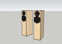
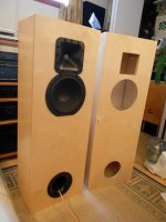
this thread is to document my first multi-way build: a 2 way with the aforementioned drivers in a MLTL cabinet. I'm really looking forward to the challenges of designing the crossover and building the cabinets, which will also be one of my first woodworking projects. Below is a sketchup model of the cabinet I'm planning to build: many thanks to IG81 for sharing details of his own 830869 MLTL for me to use as the base for my design.
I already have the drivers, ports, and other related equipment in hand so the next big project is to get started on the cabinets. But I would like to share how I modified the waveguides because I've not seen this done, and it seems to me to be a very sensible way to approach a project like this.
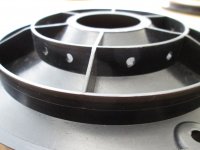
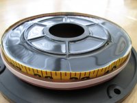
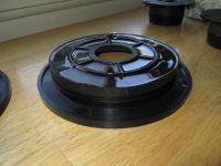
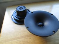
The waveguide I'm using is the Denovo DW-62S from DIY sound group (the same one that was used by Zaph for the waveguide TMM). I was inspired to go the waveguide route after studying Zaph's project, but I never much liked the idea of clamping the drivers from the back. I wanted the waveguide and tweeter to be a single unit for convenience and aesthetics. So I bought some casting resin, made a mold around the edges, and filled in the waveguide with resin as you can see in the pictures below. Just in case the resin didn't adhere to the plastic I drilled holes through the center rib so that the resin would pass through and stay in. Overall I think the finished product is attractive and it has the added benefit of being much more inert than the original. The waveguides gained an extra 5-6oz of weight.
If you go this route, each waveguide requires exactly 2/3 cup of resin. I used castin' craft easycast to make mine.
Next: some preliminary work on the crossover. While I haven't yet been able to take my own frequency response measurements, I've made FRDs of the peerless datasheet and zaph's Seas/waveguide combination to use for preliminary experimentation. While my tweeter is not the same as Zaph's, the frequency response should be very close, so I think it's safe to use that data until I make my own. The best, and simplest, result I've managed to get so far requires only 3 components: a 1.8mH coil and 10uF cap on the woofer, and a 3.3uF cap on the tweeter. The result is a smooth transition around 1.6k with a deep, symmetrical reverse null and 2db of built-in BSC. I've tried all sorts of configurations including mixtures of 3rd- and 4th-order slopes, zobels, notch filters and BSC circuits, but nothing else has worked this well on paper. One thing that baffles me is that I have not been able to get any more BSC than 2db, even with fairly aggressive BSC filters. But my room is pretty small so I hope 2db will end up being enough. One last note: according to the baffle diffraction and room boundary simulator, the cabinet I'm building will produce a slight ~1db bump around 700-1.5K that corresponds precisely with the dip in FR.
That's all I've got so far! Any feedback would be appreciated, and I'll be sure to post updates as they come.
this thread is to document my first multi-way build: a 2 way with the aforementioned drivers in a MLTL cabinet. I'm really looking forward to the challenges of designing the crossover and building the cabinets, which will also be one of my first woodworking projects. Below is a sketchup model of the cabinet I'm planning to build: many thanks to IG81 for sharing details of his own 830869 MLTL for me to use as the base for my design.
I already have the drivers, ports, and other related equipment in hand so the next big project is to get started on the cabinets. But I would like to share how I modified the waveguides because I've not seen this done, and it seems to me to be a very sensible way to approach a project like this.
The waveguide I'm using is the Denovo DW-62S from DIY sound group (the same one that was used by Zaph for the waveguide TMM). I was inspired to go the waveguide route after studying Zaph's project, but I never much liked the idea of clamping the drivers from the back. I wanted the waveguide and tweeter to be a single unit for convenience and aesthetics. So I bought some casting resin, made a mold around the edges, and filled in the waveguide with resin as you can see in the pictures below. Just in case the resin didn't adhere to the plastic I drilled holes through the center rib so that the resin would pass through and stay in. Overall I think the finished product is attractive and it has the added benefit of being much more inert than the original. The waveguides gained an extra 5-6oz of weight.
If you go this route, each waveguide requires exactly 2/3 cup of resin. I used castin' craft easycast to make mine.
Next: some preliminary work on the crossover. While I haven't yet been able to take my own frequency response measurements, I've made FRDs of the peerless datasheet and zaph's Seas/waveguide combination to use for preliminary experimentation. While my tweeter is not the same as Zaph's, the frequency response should be very close, so I think it's safe to use that data until I make my own. The best, and simplest, result I've managed to get so far requires only 3 components: a 1.8mH coil and 10uF cap on the woofer, and a 3.3uF cap on the tweeter. The result is a smooth transition around 1.6k with a deep, symmetrical reverse null and 2db of built-in BSC. I've tried all sorts of configurations including mixtures of 3rd- and 4th-order slopes, zobels, notch filters and BSC circuits, but nothing else has worked this well on paper. One thing that baffles me is that I have not been able to get any more BSC than 2db, even with fairly aggressive BSC filters. But my room is pretty small so I hope 2db will end up being enough. One last note: according to the baffle diffraction and room boundary simulator, the cabinet I'm building will produce a slight ~1db bump around 700-1.5K that corresponds precisely with the dip in FR.
That's all I've got so far! Any feedback would be appreciated, and I'll be sure to post updates as they come.
Attachments
-
 830869 MLTL updated.jpg163.4 KB · Views: 1,558
 -
 830869 27tffc 2nd order 1st order.gif26.7 KB · Views: 1,523
 -
 Waveguide with drill holes.JPG734.7 KB · Views: 1,505
 -
 Waveguides being cast.JPG795.4 KB · Views: 1,443
 -
 Finished product.JPG760.2 KB · Views: 1,394
 -
 Waveguides with tweeters.JPG902.8 KB · Views: 491
You should take measurement of the midbass in your cabinet and the tweeter too. Measure outdoors on solid ground from 5-6 fet diatance with the real cabinet to get precice effects of baffle and floor effects.
Simulations are fine for preliminary outlines of the design, but just that. Real life is different and sometimes it hels you, sometimes not.
I like Zaph's designs a lot, you should get a really fine speaker!
Simulations are fine for preliminary outlines of the design, but just that. Real life is different and sometimes it hels you, sometimes not.
I like Zaph's designs a lot, you should get a really fine speaker!
Good advice: 4uF on the tweeter and 2.2mH/15uF on the woofer controls the woofer breakup considerably more.
On the other hand, here's a simulation with 24db slopes. Again very good phase alignment, reverse null, etc, but this crossover requires 9 components instead of 3. Is it worth it? Only if the breakup on the woofer is really obvious, I suppose.
On the other hand, here's a simulation with 24db slopes. Again very good phase alignment, reverse null, etc, but this crossover requires 9 components instead of 3. Is it worth it? Only if the breakup on the woofer is really obvious, I suppose.
Attachments
Last edited by a moderator:
Interesting project! I was going to get 830869 to mate with Seas 27TDC in waveguide. I made the waveguides from POM plastic (with helpful diyer and CNC machine). (Un)fortunately I got a pair of CA22RNY's for a decent price and will try to come up with something around CA22RNY and 27TDC + wg. But I will most propably try out 830869 in the future. I have been fiddling with 5.25" and 6.5" drivers in the past and now I want to try 8" for a change.
Keep us posted with the progress.
Keep us posted with the progress.
Wow jlaakso, it sounds like we had exactly the same idea! As for me, I'm making the leap all at once from a 5" full range to this so I'm jumping over 6.5" entirely. Although I appreciated the "purity" of a no-crossover, point-source speaker, I got tired of all the compromises I had to make musically. Since I've never really minded listening to two way speakers, I decided to go with a two way for my next project. It took a lot of thought to come to the decision to make this particular speaker, and in fact, it was mostly due to finding a good deal on the 830869 woofers that I ultimately went this route.  (I had originally intended to make a "budget" version of zaph's WGTMM with 6.5" drivers.)
Troels' TQWT was also an inspiration for the 8"/waveguide floorstander configuration:

I'm even planning to overlap the woofer flange with the waveguide slightly to improve CTC spacing, although not THAT much since I don't want to route into the waveguide.
(I had originally intended to make a "budget" version of zaph's WGTMM with 6.5" drivers.)Troels' TQWT was also an inspiration for the 8"/waveguide floorstander configuration:
I'm even planning to overlap the woofer flange with the waveguide slightly to improve CTC spacing, although not THAT much since I don't want to route into the waveguide.
You could mount the Peerless sideways so that the truncated frame would face the tweeter.
I'm also considering spacing them overlapping. Not sure yet if I will. I'll propably try them without the overlap and try to measure if there is lobing. And I have always wanted to try dipoles, so I will also place them in a narrow baffle as well. This will be my first own design, if it ever gets finished or succeeds propably end up with a simple two way in ported box.
Or three way.. Or dipole.. Or omni.. Errr... anyhow, I will propably have a lot of fun and a lot of four letter words. And propably learn something on the side.
I'm also considering spacing them overlapping. Not sure yet if I will. I'll propably try them without the overlap and try to measure if there is lobing. And I have always wanted to try dipoles, so I will also place them in a narrow baffle as well. This will be my first own design, if it ever gets finished or succeeds
propably end up with a simple two way in ported box.Or three way.. Or dipole.. Or omni.. Errr...
anyhow, I will propably have a lot of fun and a lot of four letter words. And propably learn something on the side.I know that would be the more appropriate thing to do from an engineering standpoint, but I just don't like the look of the woofer mounted that way.You could mount the Peerless sideways so that the truncated frame would face the tweeter.
I know that would be the more appropriate thing to do from an engineering standpoint, but I just don't like the look of the woofer mounted that way.
I mounted the truncated sides up and down on mine, but it worked well with my square waveguide. Might indeed look better the other way with your round waveguide and the CTC spacing gain is very minimal anyway.
Good luck with the build, looking forward to see what comes out of it.
IG
Attachments
Just to get you heading in the right direction, chazdrumzalot...
You'll never get anything good with a 1.8mH coil and a 10uF capacitor on the 8" bass. 8" bass peaks badly in the midrange if you overdo the shunt capacitor, it's just how they are.
These drivers need a Zobel type capacitor shunt to get some serious rolloff. Say 7.5R and 6uF along with a suitable bafflestep coil around 2mH. I'd add a tank around 6-7kHz across the coil to dip the breakup too. In fact Troels does exactly that here:
TQWT-
Hope it helps.
Partly, I suppose, but the difficulties are mainly to do with the major cone resonance around 3.5kHz with an 8" driver which is uncomfortably close to crossover point.^is it due to above average voice coil inductance?
Most 8" drivers also have a natural steep frequency response rolloff around 24dB per octave which doesn't give you much scope with filtering or time alignment.
Using a recessed horn tweeter might help a lot here. I'd trust Troels' design as a start.
TQWT-
I tested the 830869 with a Selenium D220 coupled with a Pyle PH715 asymmetric horn. I'm quite happy with the results. A sample of my crossover can be found at Nightingale-V.
I'll be running more test, this time with a DNA350 compression driver and a selection of horns from DIY Sound Group. I think it'll be even better.
I'll be running more test, this time with a DNA350 compression driver and a selection of horns from DIY Sound Group. I think it'll be even better.
Hi System7, thanks for your informative reply. A few questions/comments:Just to get you heading in the right direction, chazdrumzalot...
You'll never get anything good with a 1.8mH coil and a 10uF capacitor on the 8" bass. 8" bass peaks badly in the midrange if you overdo the shunt capacitor, it's just how they are.
These drivers need a Zobel type capacitor shunt to get some serious rolloff. Say 7.5R and 6uF along with a suitable bafflestep coil around 2mH. I'd add a tank around 6-7kHz across the coil to dip the breakup too. In fact Troels does exactly that here:
TQWT-
Hope it helps.
In the second simulation I posted, I used a 2.2mH coil and a 15uF cap to get the woofer breakup ~14-15db below the total output. Assuming this is not enough, what minimum suppression should I be aiming for?
...Which leads to my next question:by "overdoing" the shunt capacitor are you saying that 10uF is TOO large? If that's the case, I think I already know how you'll feel about the 2.2mH/15uF option.
I initially started my crossover simulations with a zobel (the same as IG81 recommended, or by using PCD's suggested values) and baffle step and everything, and this morning I went back to that. But I have not yet found a way to incorporate the zobel such that I get a good FR, good phase, AND any additional breakup control compared to 2.2mH/15uF. To get anything that looks good I have to resort to a single series coil in conjunction with the zobel (and then phase is bad anyway). This may all be due to the fact that I'm not yet using my own in-box measurements, and perhaps once I get started with those I'll see (or hear) what you're describing.
If serious rolloff is the goal, maybe I should put more attention toward the 24db crossover, despite the higher complexity and cost.
- Status
- This old topic is closed. If you want to reopen this topic, contact a moderator using the "Report Post" button.
- Home
- Loudspeakers
- Multi-Way
- First 2-way build: Peerless 830869 8" and Seas 27TFFC in waveguide