At first glance, there are much more prominent higher and odd harmonics in the 6N1P, whereas the 6N3 seems to be mostly even harmonics. That is probably why I preferred the 6N3's warm sound. There also seem to be a number of signal/PSU ripple intermodulation products more in the 6N1 plot.
Equally it could be that the 6N1 takes much longer to break in than the 6N3?
Gary
Equally it could be that the 6N1 takes much longer to break in than the 6N3?
Gary
The noise floor seems to be a couple dB higher with the 6N3P as well. This may mask (make it look like it has higher THD) the distortion.
I'll try to do some listening tests in the next week.
I don't understand the step drop and noise above 12KHz either. It almost looks like Aliasing noise. It is present in every plot.
I'll try to do some listening tests in the next week.
I don't understand the step drop and noise above 12KHz either. It almost looks like Aliasing noise. It is present in every plot.
Yes that dropoff seems peculiar and it is not present on the plot in your previous post. Might pay to do a check on the test setup to see if something strange is happening there.
The thing (and it may be an aberration) that concerned me about the 6N1 plot is that peak at 5.5kHz. I don't know what could cause that but I bet it wouldn't sound great either.
The thing (and it may be an aberration) that concerned me about the 6N1 plot is that peak at 5.5kHz. I don't know what could cause that but I bet it wouldn't sound great either.
Hi Steve, Gary. That 5.5 kHz peak might be related to the 10.5 or 11kHz peak, must be from some piece of mains equipment nearby? An AC motor with 2 speeds maybe? Just guessing. Well I'm shattered, the Mengyue 6P1 was voted best sound by a friend this afternoon, it's the only one with mosfet source followers, and 6N1P input tubes...Good to see your progress Steve. The 6N1P has 300-330V via 150K to anode, and 2K unbypassed on the cathode. Any chance of testing that combination if you have time or are curious?
Ian.
Ian.
Sure Ian. The test set up is still on the bench so I'll wire that up next. I was wondering how using LEDs compared to traditional gain stage any way so I'll wire up your configuration next.
I'll also get a plot with the input set to zero to see what noise sources are being picked up.
I'll also get a plot with the input set to zero to see what noise sources are being picked up.
I figured I'd go ahead and trun the plots before I start digging up my water line. I just found a leak so I'll be pre-occupied for the next day or so.
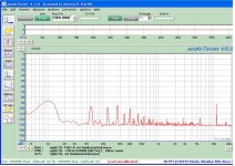
First plot is current source in anode, LED in cathode and signal generator turned down all the way.
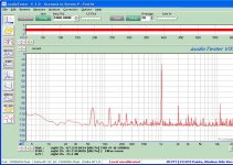
Second plot is 1vrms out with current source in anode and led in cathode.
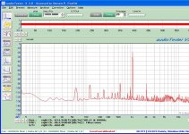
Third plot is 1Vrms out with 150K anode, 2K cathode un-bypassed.
I wonder if the spike just beyond 10KHz could be noise generated by the current source?
First plot is current source in anode, LED in cathode and signal generator turned down all the way.
Second plot is 1vrms out with current source in anode and led in cathode.
Third plot is 1Vrms out with 150K anode, 2K cathode un-bypassed.
I wonder if the spike just beyond 10KHz could be noise generated by the current source?
Attachments
Thanks a lot for that Steve, much appreciated and very interesting. Do you know if a distortion spectrum for a particular tube is characteristic of all tube output voltages, within reason of course? Or does it change a lot according to output voltage swing? Great to see you got your test gear up and running. I'm not sure yet whether I'll stay with just my ears as "test equipment", or go the next big step, time will tell. I'm having some trouble coaxing some decent sound out of a Ming Da MC34B chassis and iron (with 6P3S), I thought it was pretty good until I did some A/B testing with 2 other amps yesterday. I have a 6V/12V heater switch on the front panel so I can try out any 6V/12V input tube with the standard 9-pin arrangement. I'm on my fourth different input/phase splitter stage and going nowhere fast. I may have dubious quality cathode caps on the output tubes, so will try fixed bias and hope the tubes can take the extra B+, we will see. Best of luck with your experiments, I love reading about them.
Edit: Maybe I should do some listening tests on LED's as cathode loads on input tubes...
Edit: Maybe I should do some listening tests on LED's as cathode loads on input tubes...
Last edited:
Well, I got the water line repared, and drove an 8' ground rod while I had access to the soil near the power line service entrance since I have plastic water pipe and not copper or iron.
I built two sets of speakers that are meant to be used with the FireFLy (Single Ended Amp).
And, I think I finally finished taking measurements of the prototpye, so I built a second channel on the same test chassis and completed the power supply. It all sounds pretty good over all for such a small amp.
I did some additional tests with a cathode resistor bypassed, unbypassed, and with cathode voltage sink. The unbypassed cathode resistor had the lowest distortion, but didnt' sound the best. I'm building the first amp with a 360R cathode resistor bypassed with a 330uF 50V Cap per tube.
I'll build the second amp with a voltage sink in the cathode and then compare the amps when they are finished and I've had a chance to listen to them for a while.
Attachments
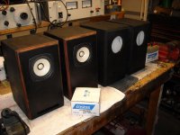
I built two sets of speakers that are meant to be used with the FireFLy (Single Ended Amp).
They look nice. I've had FE103eN mFonkens on my desktop, which were quite enjoyable. Whatever happened to your 6P1P PP amp?
Jeff
The 6P1P PP amp is up stairs driving a set of Klipsch Heresy speakers in the dining room. I listen to it when I'm cooking in the kitchen.
I need to bring it back down stairs and do some tweeking on the feedback. I may put one of these upstairs when I finish, bring the PP back down and play with it before starting my next amp.
The next amp will probably be either 6P1P PP with fixed bias and abusive voltage levels on the plates (300 to 350V), or a Parallel PP 6P1P with something like Tubelab's PowerDrive. Or possibly roll them together and get really hairy.
Last edited:
The next amp will probably be either 6P1P PP with fixed bias and abusive voltage levels on the plates (300 to 350V), or a Parallel PP 6P1P with something like Tubelab's PowerDrive. Or possibly roll them together and get really hairy.
Sounds interesting, a 6P1P V8 PowerDrive.

Jeff
I will make mine from Obsidian from Yellowstone.
Will you use PowerDrive™, or more conventional design?
I ran the FireFly™ for 6 hrs tonight and got a 34ºC rise in temp on the power transformer with two channels biased at 37mA. If I'm going to get any lower distortion I'll have to up the bias, and the only way I can see that with this transformer is to add a second transformer for heaters to off-load the B+ transformer.
I've been listening to Bonnie Raitt all evening. She sounds really good. Nice attack on drums. Steel Guitar sounds like steel, not wood. ... reasonable sound stage on "my Opening Farewell" from Sweet Forgiveness.
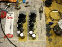
I got the power supply boards wired for two amplifiers (Both Stereo, not two channels) about finished.
The transformer is rated for 50mA at 460V CT (capacitive input) , and 6.3V @3A. I'm running it with an inductive input, and tuning the voltage with a small input cap to get 250V DC B+, so I have 80VAC across the inductor. According to my calculations I should get near 30% more current at the lower voltage this way. Transformer temp seems to confirm this.
I can leave it the way it is, or add a 6.3VAC transformer for heaters and up the bias slightly more (Maybe 40mA?). But that is starting to get on the edge design wise.
I'm using MKT film caps for the first stage (only 4.4uF) to set the voltage. As I believe they should handle the ripple better than AL electrolytic caps.
Will you use PowerDrive™, or more conventional design?
I ran the FireFly™ for 6 hrs tonight and got a 34ºC rise in temp on the power transformer with two channels biased at 37mA. If I'm going to get any lower distortion I'll have to up the bias, and the only way I can see that with this transformer is to add a second transformer for heaters to off-load the B+ transformer.
I've been listening to Bonnie Raitt all evening. She sounds really good. Nice attack on drums. Steel Guitar sounds like steel, not wood. ... reasonable sound stage on "my Opening Farewell" from Sweet Forgiveness.
I got the power supply boards wired for two amplifiers (Both Stereo, not two channels) about finished.
The transformer is rated for 50mA at 460V CT (capacitive input) , and 6.3V @3A. I'm running it with an inductive input, and tuning the voltage with a small input cap to get 250V DC B+, so I have 80VAC across the inductor. According to my calculations I should get near 30% more current at the lower voltage this way. Transformer temp seems to confirm this.
I can leave it the way it is, or add a 6.3VAC transformer for heaters and up the bias slightly more (Maybe 40mA?). But that is starting to get on the edge design wise.
I'm using MKT film caps for the first stage (only 4.4uF) to set the voltage. As I believe they should handle the ripple better than AL electrolytic caps.
Attachments
Last edited:
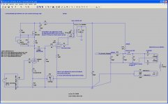
The mosfet ccts in the post below worked well for me, with the source resistors changed to 27K instead of 100K. Later variations used a CCS set to around 1.7mA instead of the source resistor. The simple version with source resistor does sound very good. I found this mosfet source follower seems to make an amp sound better even when you think you don't need it. But then, knowing you, you'll probably design your own.
http://www.diyaudio.com/forums/tubes-valves/72536-el84-amp-baby-huey-44.html
http://www.diyaudio.com/forums/tubes-valves/72536-el84-amp-baby-huey-44.html
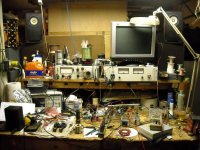
It is neat now. You should see it when I am working on something.
It is exactly what I am talking about. I currently run several projects in parallel...
I found this mosfet source follower seems to make an amp sound better even when you think you don't need it.
Because otherwise on peaks you hit grid currents suddenly, charging coupling caps.
A couple of thoughts on FET source Followers.
I used one to buffer the input tube when I was measuring distortion, but I had the cap on the output of the FET, not the input.
With the cap between the phase splitter tube and the source follower (with a negative supply), the input impedance of the FET circuit is much higher than an output tube grid ckt impedance. Thus one could use a much smaller (capacitance and physical size) coupling cap.
This has two advantages I can see, (1) cost, and (2) space in the chassis. The FET ckt is smaller than a .22uF 630V PIO, and probably most high end film or foil caps.
Is there a downside other than the added circuit complexity and Pd of the FET?
The input impedance of the FET ckt should be more constant than a tube if the tube is driven into grid conduction (Not diserable for the 6P1P). So I would view this as another advantage.
- Status
- This old topic is closed. If you want to reopen this topic, contact a moderator using the "Report Post" button.
- Home
- Amplifiers
- Tubes / Valves
- FireFly Single Ended Tetrode