sreten said:Just some suggestions :
1. Have you oiled the motor ? (as best you can).
2. Reinforcement of the main bearing :
something along the lines of :
Make a cardboard "well", triangular in shape, about 2cm high
and glue this around the main bearing. Fill the well with rigid
potting compound or thermosetting polyester resin or similar.
Other options are to extend this into a reinforcing rib towards
the arm mounting part of the subchassis. I haven't needed
to do this on turntables I've modified, but obviously there is
a lot of freedom with what you could do regarding height width
and shape. A reinforcing steel rod could also be incorporated.
3. Main platter damping. IMO easiest to achieve with the mat.
Consider using a multilayer mat with heavy rubber at the
bottom to damp both platter and subplatter.
Then experiment with material for record support on top.
sreten.
1. Yes i've oiled the motor (as good as i could).
2. Reinforcing the main bearing you say! Now why didn't i think of that myself, i'll definitely look into it!
3. The mat i use now, is the same thickness as the original one. There's not much space to work in unless i place the arm pivot higher. That is something i'm not yet comfortable with, so i'll leave it for now. However, i'm willing to try to damp the inner and outer platter though! Just got to find a solution that is to my liking.
ingvar ahlberg said:Beautifull work!
One mod that i have found to work good on Thorens decks from TD 150 and on is to fill inner platter wiyh a polyurethane potting compund. 3M has a good product sold in 250g pack. This works wonders for resolution in the bottom end as all ringing in the platter dissapeares. Do this in a well ventilated area!!!
Hi, do you know the name/number for this 3M product?
Re: Stabilizer
Hi Svein,
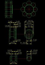
I have never held a real Thorens stabilizer in my hands, so i had to guess the measurements, but i think it's pretty accurate. I'll try to convert the autocad drawing to a picture i can post here. Give me some time, then i'll post it here.
Jerry T.
SvErD said:JerryT, your stabilizer looks like a copy of Thorens own stabilizer. Is it an accurate copy? Do you have any drawings or more pictures that shows more details of it?
svein
Hi Svein,
I have never held a real Thorens stabilizer in my hands, so i had to guess the measurements, but i think it's pretty accurate. I'll try to convert the autocad drawing to a picture i can post here. Give me some time, then i'll post it here.
Jerry T.
Attention!
As i sort of started the talk about potting compounds and such chemicals i feel the need to ask You all to observe the right precautions while using potentially hasardous products.
All 2-component curing polymers are potentially hasardous !
The polyurethane group are the "least dangerous" the epoxi the worst. Whatever You use- work outdoors or with good ventilation, use breathing protection however ridiculous it looks. I use the polyuretane group of compounds as i find them giving the best result and are the most environmental ageeable of this kind of chemicals. BUT! PLS read this: Cured polyurethane ( all kinds)
that needs to be adjusted, filed, drilled, sanded or in any way mechanicaly adjusted, is lethal! Never do mechanical work on polyurethane indoors, never without breathing protection as the dust is dangerous, pls observe this precaution. We all want to share more projects so dont neglect safety.
Yeas i have the product number at work, will post tomorrow, as long as all users pay attention to the safety precautions.Hi, do you know the name/number for this 3M product?

sreten said:Hi Raka,
The principle is the flat subchassis with the arm mass will have
a resonance against the mass of the platter, bending around
the joint to the main bearing.
(This was a major problem with the Linn LP12 and the Rega
RB300 arm. Martin Colloms (of Stereophile) recommended
epoxying a perspex block around the bearing of the LP12
to address this.
Later Linn added a reinforcing rib to the subchassis)
The purpose of the reinforcement it to prevent this resonance,
and replace it with a higher frequency more damped coupling.
Similarly extending the reinforcement into a rib towards the arm
is to modify the resonant behaviour of the subchassis and reduce
any bending modes of the flat subchassis.
Try at your own risk of course............
I can't see why the resin wouldn't be suitable, though polyester
resin has various grades, from quite soft to hard and brittle.
Thanks for elaborating on that. Interesting thing, indeed. I don't see why there should be risk on that, but a difficult thing to optimize, so I'll spend some time with that.
I'm thinking that if the rib goes from the arm, alongside the bearing, and towards the other end of the subchassis, (potting the bearing), I could get a rigid subchassis that can be also damped with felt. Maybe it's easier to build a new subchassis...
BTW, my DIY stabilizer is made of brass and not so beautiful as yours. Well, if you like the russian panzers maybe you like it.
Raka said:
Thanks for elaborating on that. Interesting thing, indeed. I don't see why there should be risk on that, but a difficult thing to optimize, so I'll spend some time with that.
I'm thinking that if the rib goes from the arm, alongside the bearing, and towards the other end of the subchassis, (potting the bearing), I could get a rigid subchassis that can be also damped with felt. Maybe it's easier to build a new subchassis...
JMO : felt is a poor damper of steel, vinyl floor tiles are better.
Regarding the rib : as outlined it will modify bending modes most.
IMO it should enclose the main bearing to provide torsional
stiffnees as well, that is bending modes across the subchassis.
this sort of shape perhaps (not to scale) ;
sreten.Attachments
thanks for the drawing
What material could be used for the rib? a square extrusion of aluminium (some mm²), and potted with the polyester? because using soldering (but using Fe, not Al) is a bit over the edge, isn't it?
I don't understand very well the drawing, what are the small lines? what are "bent pins"
What material could be used for the rib? a square extrusion of aluminium (some mm²), and potted with the polyester? because using soldering (but using Fe, not Al) is a bit over the edge, isn't it?
I don't understand very well the drawing, what are the small lines? what are "bent pins"
As I understand it the subchassis is steel so a
piece of threaded steel rod would be best IMO.
Steel pins and needles are used for sewing.
I meant bend them slightly in the middle.
Thats what the blue lines are.
Alternatively you could use some thread (cotton / nylon)
passed through the well (with a needle) glued in place.
The rod is suspended clear of the subchassis near
the top of the well to have maximum effect.
hope that helps, sreten.
Attachments
Hi,
Plastic will hardly resonate, so all you probably achieve by making it heavier is an increased risk of reducing bearing life and random eccentricities in the subplatter.
Cheers,
Could I fill that with silicone or latex caulk done in layers as it would take forever to cure if done in all one shot? Has anyone tried this? Any opinions?
Plastic will hardly resonate, so all you probably achieve by making it heavier is an increased risk of reducing bearing life and random eccentricities in the subplatter.
Cheers,
Hi,
Agreed, I was really thinking about bearing noise. I probably would have ended up with a 5 inch, 1lb. hockey puck. Not sensible.
Thanks
Wayne
Plastic will hardly resonate, so all you probably achieve by making it heavier is an increased risk of reducing bearing life and random eccentricities in the subplatter.
Agreed, I was really thinking about bearing noise. I probably would have ended up with a 5 inch, 1lb. hockey puck. Not sensible.
Thanks
Wayne
Hi,
If you want to reduce bearing noise try some fine machine oil and in case you can find it add a droplet of PTFE suspended in oil.
Realistic used to have a something like this as a lubricant for god knows what.
Different grades of oil will make for quite marked audible differences IME.
Cheers,
Agreed, I was really thinking about bearing noise.
If you want to reduce bearing noise try some fine machine oil and in case you can find it add a droplet of PTFE suspended in oil.
Realistic used to have a something like this as a lubricant for god knows what.
Different grades of oil will make for quite marked audible differences IME.
Cheers,
- Status
- This old topic is closed. If you want to reopen this topic, contact a moderator using the "Report Post" button.
- Home
- Source & Line
- Analogue Source
- Finished modifying Thorens TD 160!