Go to the Basic Transformer Design section of the following page. There's a calculator there.
Basic Switching Power Supply Design Tutorial
Basic Switching Power Supply Design Tutorial
No,risto's suppy IS regulated, it has feedback. opto+2x zener
can someone give me link of this schematic or post where it is
because risto's smps on first page doesn't have feedback on TL494
Other threadcan someone give me link of this schematic or post where it is
because risto's smps on first page doesn't have feedback on TL494
http://www.diyaudio.com/forums/car-audio/31614-making-car-amplifier-smps-tl494-dc-protection.html
and it is with SG3525, not TL, but similar IC
Would this be a suitable core for a 300W high current amp? I'm wanting to build a 2 channel old school "cheater" amp that can go down to 0.5 loads. Power at 4 ohms to be around 20 Wrms per channel. I'll go with a unregulated supply of around +/-15 volts. At 1 ohm mono I would like about 300 Wrms.
Attachments
this might be ok yes, looks big enough, make sure its power material... and you will see what freq. you would need, I think 40k would be good to start, maybe you would need less... and make sure, if unregulated, that when voltage drops, you still have enough for your amps
Other thread
http://www.diyaudio.com/forums/car-audio/31614-making-car-amplifier-smps-tl494-dc-protection.html
and it is with SG3525, not TL, but similar IC
in which post is final and tested smps circuit with feedback control, because I can read in later posts that some schematics on start have bugs?
I don't know what final, what does final for this supply even mean, anyway I made several of the one on first pagein which post is final and tested smps circuit with feedback control, because I can read in later posts that some schematics on start have bugs?
What do you think about this one?
100W Car Subwoofer Amplifier
If only I could add voltage feedback control on TL494?
Do you have idea how to implement fb to it?
100W Car Subwoofer Amplifier
If only I could add voltage feedback control on TL494?
Do you have idea how to implement fb to it?
JLH:
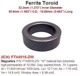
I don't think the W material is going to be suitable for a power transformer. The F and P materials are good choices (P is my choice when I build supplies). Contact the manufacturer or distributor if you decide to use the W material to see if they believe it's suitable for a power transformer.
I don't think the W material is going to be suitable for a power transformer. The F and P materials are good choices (P is my choice when I build supplies). Contact the manufacturer or distributor if you decide to use the W material to see if they believe it's suitable for a power transformer.
The below quote is from Perry's web site. I've Googled around, but cannot find any references to the 20% winding factor for toroidal cores. What is the rationale for it? Is it a known good balance between copper losses and good magnetic coupling between primary and secondary? At face value it makes me think about the primary copper losses more than anything.
OK, now that you basically know how much copper you need (considering the duty cycle, maximum power and current draw), you have to have a core that can hold the primary and secondary windings. Many times, the primary and secondary will have approximately the same amount of copper on the primary as on the secondary. If you have a transformer with a 1:3 ratio, the length of wire for the secondary will be three times as long as the wire on the primary but the current passing through it will be 1/3 as much so the circular mils of the secondary will be 1/3 that of the primary. For this supply, the secondary uses a single 14g wire where the primary uses three parallel 14g conductors. What this means is that the core will have to hold approximately double the copper used for the primary alone. For toroidal cores, the 'winding factor' is generally 0.2 (20% of the window area filled with copper). It can be more or less but this is typically what's used in the various calculations.
if you really need feedback, it would be done pretty much the same as with SG
find one that has TL and has feedback... I think you will only need hand full of components more for that
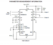
TL494 has DTC pin 4, Feedback pin 3, 4 inverting/noninverting pins 1,2,15,16, I've attached image from datasheet.
I'm confused which all pins are for U an I control???
Attachments
The 0.2 winding factor is for the primary. It's not critical.
Page 4:
http://www.mag-inc.com.cn/file library/products/ferrite/power_design.pdf
Page 4:
http://www.mag-inc.com.cn/file library/products/ferrite/power_design.pdf
The 0.2 winding factor is for the primary. It's not critical.
Page 4:
http://www.mag-inc.com.cn/file library/products/ferrite/power_design.pdf
That's a really nice tech paper. What I find most interesting is how little capacitance and inductance is required at these higher switch frequencies. In one of my SMPS examples I calculated 4.9uF and 1.4mH. Due to the waves being square instead of a sine wave, once rectified there's not much left to do because its basically DC at that point. We just need to clean up the ringing and noise. I also see why having a perfect 50% switching duty cycle for the MOSFETs is so critical. These SMPS are very interesting beasts.
protection unit
Hello risto..its great work you have done here.i.have seen all 3 pcb and schemes.all are nicly done.the only thing i am not able to understand is the protection unit of the amp .it will be very helpfull if you post a conection drawing of protection unit with amp and smp..regards sohail
Hello risto..its great work you have done here.i.have seen all 3 pcb and schemes.all are nicly done.the only thing i am not able to understand is the protection unit of the amp .it will be very helpfull if you post a conection drawing of protection unit with amp and smp..regards sohail
- Status
- This old topic is closed. If you want to reopen this topic, contact a moderator using the "Report Post" button.
- Home
- General Interest
- Car Audio
- Finished Car Amplifier schematic + PCB based on Kenwood KAC-716