Yieeeeeeeehhhhhhaaa
At least the amp sound as I wanted!!!
The sound is normal with 0.47 µF, and warm with 1µF; so I'll took the 1µF of course (😉); for higher sounds use 0.25µF.
I think I will use these three values with a switch, so you can adjust the amp to your speakers with the switch.
Hey, do I hear CCR 'live' in my hobby-room 🙂 ???
HB.
Now, I've got even better sound with the 0.47µF input cap (1µF was too heavy with some songs), and a 100µF placed over the biasing circuit.
Tomorrow I will add the MJ15003/15004 transistors to the circuit, how many should I place in parallel to play with 4 ohm load (or bridged 8ohm)??
HB.
Tomorrow I will add the MJ15003/15004 transistors to the circuit, how many should I place in parallel to play with 4 ohm load (or bridged 8ohm)??
HB.
You would probably manage with 2 transistors for a long time but to be on the safe side, use 3 in parallel.
/Marcus
/Marcus
I'm think to use 4 PCB's in total with each 4 transistors
So, that will make 16 transistors in total, and the acht plastic ones, for the bridged stereo-version, which can will drive 8 ohm load.
woooh, I've made that heatsink + fans already, and have also the necessary supplies and the caps, so I only need to make 3 another PCB's. That will take about two or three weeks to make that PA-amplifier I always wanted.
I will publish some pictures if it is so far...
HB.
I'm just wondering how many watts I can drive with my eight transformers: 8 x 120VA (30V (220V) 34V(230V)).
I calculated 250W (x 2 => stereo). I'm just wondering if I can get more out those transformers or not?
HB.
I calculated 250W (x 2 => stereo). I'm just wondering if I can get more out those transformers or not?
HB.
Dear Hugobross,
Congratulations! U might have finalised all the component values of the amp till now. Can u kindly publish final circuit and it's pcb layout for those who are interested. I am one of them.
Mahendra Palesha
Congratulations! U might have finalised all the component values of the amp till now. Can u kindly publish final circuit and it's pcb layout for those who are interested. I am one of them.
Mahendra Palesha
hey thanks,
the amp works fine but I want to change some things ( 😉 ).
As I've told the TIP142/147 are not enough (they blew again when I made a little mistake with setting up the bias...).
So, I think I'll get me some new components thursday or friday.
This is what I've got in mind to change:
*)when I have my new TIP's I can add the Mj15003/15004's too
*)change the bootstrapping thing (R9-R8-C5) into a current source
*)change the bias diodes and the potmeter by a fixed resistor; I will try to make the current of the current source depending of the temperature with some diodes (and a resistor) in front of the base of the current source (transistor)
*)so I have to make a new pcb too
I will publish the whole new schematic as soon as possible...
HB.
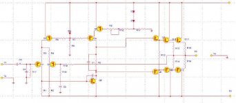
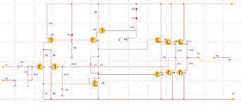
the global view of the new schematic
I think you are missing something that should be connected to Q3 and Q5. Think what they do in the circuit......... No help from the audience please!
H.H.
I think you are missing something that should be connected to Q3 and Q5. Think what they do in the circuit......... No help from the audience please!
H.H.
Re: the global view of the new schematic
Harry:
Very important point. Got your ruler ready to rap some knuckles?😀
Harry:
Very important point. Got your ruler ready to rap some knuckles?😀
😀HarryHaller said:I think you are missing something .....
What do you mean? The function of Q3 and 5 here is
clearly to implement smoke generation, very popular
with many DJ's.
clearly to implement smoke generation, very popular
with many DJ's.
smoke generation - I love it, heh, heh, heh. You guys are brutal 🙂
Nelson Pass said:... The function of Q3 and 5 here is
clearly to implement smoke generation....
to implement smoke generation
Hey don't antagonize the newbies or you will upset someone.....
By the way, I'm only a part time saint.
H.H.
Hey don't antagonize the newbies or you will upset someone.....
By the way, I'm only a part time saint.
H.H.
- Status
- Not open for further replies.
- Home
- Amplifiers
- Solid State
- FINALLY I modified it