Youhoooooo I m the only one red... I m special
It's just a reminder to me to do not forget the CD. Your goods will be delivered Monday as well.
Regards,
Tibi
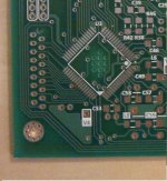
Finally more or less finished, and sounding good
An externally hosted image should be here but it was not working when we last tested it.
An externally hosted image should be here but it was not working when we last tested it.
Last edited:
An externally hosted image should be here but it was not working when we last tested it.
An externally hosted image should be here but it was not working when we last tested it.
My main problems where all my own doing. nothing as obvious as bad solder joint or wrong value components.
First big problem was cause by testing on a damp piece of wood wich caused all kinds of problems. Frankly very silly on my part.

Second problem the puck I was using was recovered from a 15 year old boombox it had so much play in it that sometime it worked and sometimes it did'nt. changed the motor spindle to one with 3 ball(no puck) and all is good
I placed the transformer in another box, really dont like transformers near anything else.
I tried to figure out the lcd saturation thing but as far as I can tell all the relevant traces are under the LC chip so unless somebody can enlighten me I'm just gonna have to live with it as is.
Old CD most of mine are over 15 years old tend to have issues mainly scratches which cause skips one CD would not even read TOC it had wierd mould under the plastic.
New CD will play from start to finish perfectly.
First big problem was cause by testing on a damp piece of wood wich caused all kinds of problems. Frankly very silly on my part.
Second problem the puck I was using was recovered from a 15 year old boombox it had so much play in it that sometime it worked and sometimes it did'nt. changed the motor spindle to one with 3 ball(no puck) and all is good
I placed the transformer in another box, really dont like transformers near anything else.
I tried to figure out the lcd saturation thing but as far as I can tell all the relevant traces are under the LC chip so unless somebody can enlighten me I'm just gonna have to live with it as is.
Old CD most of mine are over 15 years old tend to have issues mainly scratches which cause skips one CD would not even read TOC it had wierd mould under the plastic.
New CD will play from start to finish perfectly.
blueworm can you provide the source for your chassis? looks really nice
Easy question, with nice awnser for those on the other side of pond.
The case is from Par Metal, New Jersey. Series 20.
Par-Metal
An externally hosted image should be here but it was not working when we last tested it.
I had to shoe horn that bad boy. I was completeally unable to solder a 0805 resistor there. Any smaller and well "If I cant see I cant solder it."
Thats a lot better. but the angles are still rather annoying. Oh well.
blueworm, good to see you got it going.
Here is a pix of where to cut. Be careful and use a sharp pointed X-acto (Razor knife/scalpel...).
The trace is very short. The via is to power. Put the resistor from the via to the pin and don't add a cap.
Placing the resistor in that place is not the best option because LC78601 pin 22 will be affected as well and this may degrade DSP performance.
The mod can not be performed if LC78601 was soldered.
You need to perform the mod before soldering this chip.
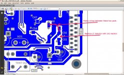
First you need to cut the trace between pin 40 and pin 22 as per top_modification.jpg - left picture.
Than, turn the board on bottom and perform the modification as per bottom_modification - right picture. Instead L7 put a 1K2 resistor or a 2K potentiometer to get your preferred contrast and make a strap between two pads. The strap will bring back Vcc to pin 22.
That´s all.
Regards,
Tibi
Attachments
Last edited by a moderator:
Not yet, but I plan to do so.
Regards,
Tibi
Hi, Tibi
Thanks in advance.
Clarence
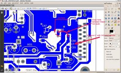
Ok, I found another solution who will work for everybody.
All modifications are only on the same side of the board, so no need to do prior mounting LC78601 and the mod can be applied to existing Shiga´s as well.
Cut near C60 as in attached picture. You may need to unsolder C60. This will separate power supply pin 22 from pin 40.
Replace L7 with an 1K2 resistor and strap two pads in order to power back pin 22.
That´s all.
Regards,
Tibi
Attachments
Last edited by a moderator:
I really hope the one that is reading well is from me.
There are several manufacturers who made this transport. Some of them are using original laser and pin diodes from Sanyo, others not.
Have a look in datasheet page 12.
http://vicol-audio.ro/docs/DA11VZ.pdf
During operation you can measure the voltage on J1 connector between 11 and 12 and adjust other mechanics the same.
Please let me know the results.
Regards,
Tibi
Hi Tibi,
Everything is ok now. I was using a other strip from 'kotobo' to connet the laser-mechanic. Now I am using yours and now the shiga plays all my CD's very well, without even 1 scratch. Super ! And the sound is sublime.
I use on the output a buffer stage with 74hc04 and a AudioNote transformer.
Audio Note
Tibi, much thanks for such good work !
- Home
- Source & Line
- Digital Source
- Finally, an affordable CD Transport: the Shigaclone story