The PS board has been described here: http://www.diyaudio.com/forums/showthread.php?postid=1237672#post1237672 that is for full bridge.
If you are using two rectifiers only, just follow schematic and connect with main board section accordingly.
If you are using two rectifiers only, just follow schematic and connect with main board section accordingly.
Audio1st/Johnm. Have either of you (or maybe both) replaced the 16.93 crystal, if so where did you source them from. I would also be interested to know if you have done all the mods suggested by Okapi, and what have you replaced them with e.g black gates, Oscons, Panasonics ?
I have got mine up and running in my test system and will run it in before I attack it or put it in my main system.
I have got mine up and running in my test system and will run it in before I attack it or put it in my main system.
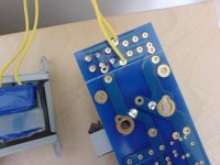
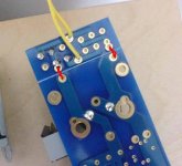
Sorry Peter I'm having an evening of 'brain fog'!!! Would you mind taking a look at my pic of the PSU and indicating where I need to make the joins?
Think I'm getting confused as this transformer has no CT as it's the stock item that came with the JVC.
Thanks,
- John
Think I'm getting confused as this transformer has no CT as it's the stock item that came with the JVC.
Thanks,
- John
Attachments
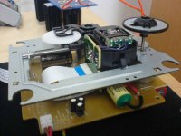
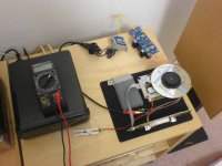
A few pics of my Shigaclone - next adventure will be the chassis ")
Puffin I used the following items:
Black Gate 1000uF / 50V standard (x 2) for the PSU board (board ordered from Peter). LM7808CT regulator, with two MUR860 diodes.
On the main circuit board I used the following:
C939 (E1) - 100uF / 63V Elna Silmic ARS
C953 (E2) - 330uF / 50V Panasonic FM
C929 (E3) - 4.7uF / 50V Black Gate N
C934 (E4) - 4.7uF / 50V Black Gate N
C916 (E5) - 47uF / 50V Black Gate N
C906 (E6) - 0.1uF 400V Auricap
Cheers,
- John
Attachments
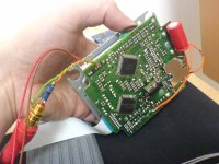
Puffin, I am using a crystal from an old Yamaha CD player (Marantz & Phillips may be the same) with one board and left the other boards crystal as standard. I think John got his from Peter, or you can get one from DigiKey for £17.43, inc p&p.
I just used Panasonic FC's for the power supply and added some FC's on the board as well.
I think the transport just sound brilliant anyhow..
I just used Panasonic FC's for the power supply and added some FC's on the board as well.
I think the transport just sound brilliant anyhow..
johnm said:Would you mind taking a look at my pic of the PSU and indicating where I need to make the joins?
Here you are
Attachments
Johnm. Your pics are good. Did you run the transport in standard form and if so how do you rate the mods ?
It looks as though you have been able to ditch the large main board ? (or is it hidden somewhere). If you have, can you explain how, and where you picked the PS supply from to power the spindle etc
What's in the grey sock like thing ?!
It looks as though you have been able to ditch the large main board ? (or is it hidden somewhere). If you have, can you explain how, and where you picked the PS supply from to power the spindle etc
What's in the grey sock like thing ?!
Thanks Puffin
Yes I used the system for a couple of days before I did the mods and I loved the sound. I almost decided to continue without the upgrades... but you know this DIY lark - in for a penny in for a pound (if only it was just a pound!).
If you search this forum for Otapi's PDF it will explain how to wire up the unit with the mods.
I haven't heard it modded yet - ask me again in another 30mins
P.S. The sock thing is my iPod - keeping the transport steady!
Johnm, sorry what I meant was (ditched i.e not using it)
In the original case the PS for the Transport comes off the main board. I assume that you have taken the supply direct from the new power supply, to the connector previously coming from the main board.
It also looks as though the PS for the display comes off the main board, if so how are you now powering this ?
Puffin, that PDF file Otapi posted will tell you everything you need to know about this. I can't remember what page it's on off-hand - try running a search for all posts by Otapi.
Yep running it without main board, and the power for the LED comes off new PSU board just after rectifiers.
- J
Yep running it without main board, and the power for the LED comes off new PSU board just after rectifiers.
- J
- Home
- Source & Line
- Digital Source
- Finally, an affordable CD Transport: the Shigaclone story