On the contrary.....nothing subtle here....I found it a huge improvement...
So the bottomline is that such improvements (or not !!) can only be judged by yourself..... that means exactly...DIY..
As Peter states it goes a step further and gets more complicated
with all the risks involved of failure....so be warned.
If you have a spare box it will be easy to cut the switch out of the pcb with the piece of pcb with the motorholes still in ....thus anligning it perfectly again...as if nothing happened...
surfstu said:is the ez51 suitable for this mod?
yes i did build mine on the ez51, the disply pcb is a litle diffrent , but nothing to worry about
pinouts are the sameAttachments
surfstu said:thats great valo...
so all i have to do is follow the pdf instructons at the begining of ths thread exactly...
the pcb's that need modding are all the same?
stuart
You can do all the mods on the EZ51, but one tip.. read every page in this thread, and when your done reading start banging on youre transport

leoparleur said:Hi Peter!
While you are here Peter, have you tried the motor upgrade by separating them from the PCB? If it makes up for better sound I'll go for it but I'm a bit puzzled on how to prolong the switch.
Thanks,
Guy
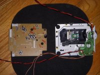
You could also get a laser/mechanics that look like this.
This laser I got out of rcbx33
Attachments
Fellows, thanks again for the help.
I see, I also prefer simpler but if it gives a bit of improvement then I'm in to proceed. I wouldn't try if it were to hard or time consuming. The only thing I'm slightly concerned about is to accommodate the switch. I'm thinking about leaving it in place and extending it with a small piece of Lexan over it to reach the limiter. I'll check later tonight as of feasability.
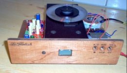
BTW, again, that is quite a nice piece of equipment you got there. It has a rugged look.
Hi Erik, nice to meet you! :0)
First, congradulations on all the nice work you do and secondly for sharing it with all the people. Your pictures are like a strawberry cheese cake to my eyes.
I understand that only me will be able to evaluate if it was a good choice. As I trust your ears and experience, I wanted to have an opinion of what you guys heard different between on or separated motors from PCB. I'm convinced that there is a noticeable difference between your Shigaclone and a simpler one but what about the one with the basic upgrade?
For sure, I'm about to get an extra boombox for spare parts. One day or another something will probably happen.
Kierownik, thanks for your input. In your picture is that the RC-EZ31 PCB or the 33 one? I guess whatever similar cd transport must have this sort of switch.
Continue the nice work guys, good night I'm heading for the garage. ;0)
Peter Daniel said:I didn't want to go into separating the motors, while it may offer subtle improvement I prefer to keep things simple. Besides, I already have another transport with well separated motors
I see, I also prefer simpler but if it gives a bit of improvement then I'm in to proceed. I wouldn't try if it were to hard or time consuming. The only thing I'm slightly concerned about is to accommodate the switch. I'm thinking about leaving it in place and extending it with a small piece of Lexan over it to reach the limiter. I'll check later tonight as of feasability.
BTW, again, that is quite a nice piece of equipment you got there. It has a rugged look.
Erik van Voorst said:On the contrary.....nothing subtle here....I found it a huge improvement...
So the bottom line is that such improvements (or not !!) can only be judged by yourself..... that means exactly...DIY..
As Peter states it goes a step further and gets more complicated
with all the risks involved of failure....so be warned.
If you have a spare box it will be easy to cut the switch out of the pcb with the piece of pcb with the motorholes still in ....thus anligning it perfectly again...as if nothing happened...
Hi Erik, nice to meet you! :0)
First, congradulations on all the nice work you do and secondly for sharing it with all the people. Your pictures are like a strawberry cheese cake to my eyes.
I understand that only me will be able to evaluate if it was a good choice. As I trust your ears and experience, I wanted to have an opinion of what you guys heard different between on or separated motors from PCB. I'm convinced that there is a noticeable difference between your Shigaclone and a simpler one but what about the one with the basic upgrade?
For sure, I'm about to get an extra boombox for spare parts. One day or another something will probably happen.
kierownik said:
You could also get a laser/mechanics that look like this.
This laser I got out of rcbx33
Kierownik, thanks for your input. In your picture is that the RC-EZ31 PCB or the 33 one? I guess whatever similar cd transport must have this sort of switch.
Continue the nice work guys, good night I'm heading for the garage. ;0)
Re: spdif out?
It is spdif, and while I haven't looked at the chipset in a while I don't believe any other signals are available - the dac is part of the digital processor chip. The quality of the spdif output is really pretty good, and if you want really low jitter and low jitter master clock and a D type flip flop to reclock the spdif signal at the output should be about as good as it gets.
BigE said:What sort of output does this produce? Is it spdif?
I've read elsewhere that it's not I2S -- that is really a shame, a WM8804 I2S to Spdif chip with 50ps jitter would be killer. Is it just shifted? ie right/left justified?
It is spdif, and while I haven't looked at the chipset in a while I don't believe any other signals are available - the dac is part of the digital processor chip. The quality of the spdif output is really pretty good, and if you want really low jitter and low jitter master clock and a D type flip flop to reclock the spdif signal at the output should be about as good as it gets.
leoparleur said:Fellows, thanks again for the help.
Kierownik, thanks for your input. In your picture is that the RC-EZ31 PCB or the 33 one? I guess whatever similar cd transport must have this sort of switch.
Continue the nice work guys, good night I'm heading for the garage. ;0)
Hi Leoparleur
It's ez51 pcb. Laser and motors are also from that unit. Rcbx33 has the right laser but the main board is useless. I just transplanted the small pcb that ties the motors together and locates the limit switch in the right place from 33's to 51's optical pickup. And the rest are just spare parts.
Hi folks
Been away from this thread for a while as I've been basking in the fine music from my PC/Trends UD10.1/Chinese 'BIG' DAC (see 'Any experience with this DAC thread').
However I want to get my Shigaclone up and running again.
I went through all my original posts and came to the conclusion I liked the sound of the Shiga best in stock form (with the exception of the 47uF Black Gate N for C916).
Fortunately I kept all the original caps so replacing them has been easy. However, I have three 220uF caps - two are marked 16V, the third is marked 25V.
Which position should the 25V item take please - I've lost my original (pre-mod) photos of the main board
Many thanks!
- John
kierownik said:
Hi Leoparleur
It's ez51 pcb. Laser and motors are also from that unit. Rcbx33 has the right laser but the main board is useless. I just transplanted the small pcb that ties the motors together and locates the limit switch in the right place from 33's to 51's optical pickup. And the rest are just spare parts.
Hi kierownik!
That is good info to consider. Yesterday, while working I thought about using the door switch, it's similar except that it's not in clear plastic housing and that it's a tid bit more tense to get contact. Properly implemented I guess it should work. Don't know why it hasn't been mentioned here before to reuse it. Plus it has the mounting hardware provided with it. It should be quite easy to adapt it and provide adjustement like Erik suggests.
DaveM said:Start by pulling the little plastic cover off so you can see the LED. I mean the clear plastic piece that has a bit of white covering the LED. Then De-solder it from the other side. It should come out pretty easily.
Peter Daniel said:The white plastic frame for display is attached with two screws and two plastic snap in tabs. You may pull it off a bit, but you won't be able to remove it completely, unless you desolder all 12 or so pins from display window, which need to come off first.
To get access to a LED pulling it off a bit may be sufficient though. The LED is soldered to the PCB.
Peter, I wasn't able to lift enough the plastic frame because of the IR sensor blocks it in place on the right side. I would have needed to go further and unsolder it to try this method. I later tried DaveM's method and worked fine. I lifted a bit the clear lens on the left extremity and unsnapped the 2 white plastic tabs. Display is now purple. :0)
just ordering some parts for resistors... not sure about the spdif output,
should i be putting a 291ohm resistor in series and another 100ohm shunt resistor to ground after it?
does this need to be done on both spdif connections i.e. core and sheaf?
and i am ordering from farnell who only have 294R and 100R, i presume this is ok?
and do i need to be buying any particular kind of spacers/ standoffs to mount the whole thing?
cheers stuart
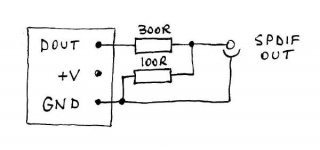
No need to drill anything. There is a spot for an onboard socket as in attached schematic; this is how the output should be connected.
I use 300/100R combo (Dale) and the values here are not really critical.
As to standoffs, I find 1" tall, 3/8 dia work well for me (2 support points only)
I use 300/100R combo (Dale) and the values here are not really critical.
As to standoffs, I find 1" tall, 3/8 dia work well for me (2 support points only)
Attachments
Thank you Peter!
So, the minimum work to get the spdif output is to install the two resistors and an RCA jack!
Cool. I can hear it working before any changes get made.... Then make one at a time and evaluate.
I can't wait to get it.... Wednesday May 6 is the arrival date.
So, the minimum work to get the spdif output is to install the two resistors and an RCA jack!
Cool. I can hear it working before any changes get made.... Then make one at a time and evaluate.
I can't wait to get it.... Wednesday May 6 is the arrival date.
BigE said:So, the minimum work to get the spdif output is to install the two resistors and an RCA jack!
Yes, that's it.
Peter,
I removed all the components identified on page 1 and 2 of Okapi's document except for the 2 side by side SMD caps identified as "2". I'm a bit confused as if I need to remove them or not, I can't seem to find the post that says not to remove them and why not to.
Also I haven't got any reply (post #3373) regarding the 2 sync wires, do you happen to know if they are necessary?
Have a nice day!
- Home
- Source & Line
- Digital Source
- Finally, an affordable CD Transport: the Shigaclone story