Starting to build a power supply for first attempt at Rod's shunt cascode RIAA circuit and the two filter chokes I have on hand for an LCLC filter are both dual coil (Lundahl).
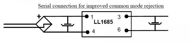
The data sheets suggests using one coil in B+ leg and the other in ground return for CM rejection. You can also use one of them for choke input. This got me to wondering - If there is an inductance between the first filter capacitor's neg. and the rectifier neg. why wouldn't we consider that an unwanted impedance in the ground return?
Common mode rejection would be a nice addition to a phono stage power supply but what would be optimum? First L in HV string only and second L in the CMR configuration? Both L's one way or the other?
Any thoughts?
Common mode choke/inductor is more commonly used on the mains cable before it gets inside your chassis.
The can around a mains filter makes metal to metal contact around the hole that the can fits through. This can effectively makes the common mode filter OUTSIDE the Chassis. That is the best place to prevent extra interference getting to the circuits inside the Chassis.
The can around a mains filter makes metal to metal contact around the hole that the can fits through. This can effectively makes the common mode filter OUTSIDE the Chassis. That is the best place to prevent extra interference getting to the circuits inside the Chassis.
This got me to wondering - If there is an inductance between the first filter capacitor's neg. and the rectifier neg. why wouldn't we consider that an unwanted impedance in the ground return?
Fortunately, that's not the case- the impedance is inserted after the first capacitor. If you have the same impedance in both legs, it's essentially balanced and that means common mode reduction. IME, it's most useful for heater supplies taken from a heater winding on the main HV transformer.
Fortunately, that's not the case- the impedance is inserted after the first capacitor.
Yes, in the data sheet drawing . . .
. . . but let's say an unsuspecting and entirely innocent user (no one by that description around here!) looked at data sheet and thought, "OK, it says here that this choke is good for choke input duty so I'll use the common mode reduction hookup in a choke input filter.", then the common practice of returning signal or star grounds to the negative terminal of the first filter capacitor comes under question because there's an impedance between it and the rectifier. That's what I'm asking about.
Hi!
You can use these chokes in CMR connection for both choke input and cap input filters. The terminal 6 of the choke becomes your signal ground. It doesn't matter if there is a inductive connection from there to the rectifier minus terminal or transformer center tap. What is important is that everything that is supposed to be on signal ground has a low impedance connection
This isn't really common practice this is actually bad practice.
Best regards
Thomas
You can use these chokes in CMR connection for both choke input and cap input filters. The terminal 6 of the choke becomes your signal ground. It doesn't matter if there is a inductive connection from there to the rectifier minus terminal or transformer center tap. What is important is that everything that is supposed to be on signal ground has a low impedance connection
the common practice of returning signal or star grounds to the negative terminal of the first filter capacitor
This isn't really common practice this is actually bad practice.
Best regards
Thomas
I don't think a common mode choke has much usefulness in tube circuits; in the 50's schematic diagrams, you would never see one (unless I am mistaken).
Their main purpose today is to allow a piece of equipment to pass EMC tests without too many issues (ie, block the internally generated crud from contaminating other nearby equipments).
If you really want to suppress common mode, a differential choke like the one you show is a very expensive and ineffective option: using current compensation, a true CMC can be much more effective, smaller and cheaper than a differential choke used in this role. But the real question is: do you actually need CM suppression? What benefits do you think it will bring?
This isn't really common practice this is actually bad practice.
I'm not sure why you are saying that. Could you say more? Whenever you have a series of RC or LC filters, all the capacitor Neg. terminals in the string are connected. What I meant was making the first filter capacitor neg a star point.
If you really want to suppress common mode, a differential choke like the one you show is a very expensive and ineffective option: using current compensation, a true CMC can be much more effective, smaller and cheaper than a differential choke used in this role. But the real question is: do you actually need CM suppression? What benefits do you think it will bring?
I don't know that it's needed, but in a phono stage if noise reduction without a catch is being offerred for free (I already have the Lundahl) then it makes sense to use it. So that was my question - is there a reason not to.
I don't know anything about current compensation. Used more in sand circuits than tube (and those are more sophisticated than I have done), I have no experience. Would you give an example of how you might do it?
It'll bring your noise down a bit. Also since you already have them, go ahead and wire them up for CME. It offers no drawbacks versus using it in series not CME. Just follow the suggested wiring as per the datasheet.
Your other option is to wire LCLC filter using the two halves of one of the chokes. Or both! Then see which you like.
Your other option is to wire LCLC filter using the two halves of one of the chokes. Or both! Then see which you like.
Do you mean like in the data sheet (without the input capacitor)?
with input capacitor, then the other capacitor served as the psu common, that one goes to the central ground point....
It'll bring your noise down a bit. Also since you already have them, go ahead and wire them up for CME. It offers no drawbacks versus using it in series not CME. Just follow the suggested wiring as per the datasheet.
Your other option is to wire LCLC filter using the two halves of one of the chokes. Or both! Then see which you like.
i make all transformers and chokes in all my amp builds, making these chokes is easy for me...
i am happy to use these CM chokes, but i do not go around telling people that this is what they should use.....
Hi!
What I mean is not to use the negative Terminal of the first capacitor in that string as a star ground point. You have the most ripple current flowing through that point. Better is to connect the negative terminals of the caps in the PSU string in bus fashion and use the terminal of the last cap as star ground
Best regards
Thomas
I'm not sure why you are saying that. Could you say more? Whenever you have a series of RC or LC filters, all the capacitor Neg. terminals in the string are connected. What I meant was making the first filter capacitor neg a star point.
What I mean is not to use the negative Terminal of the first capacitor in that string as a star ground point. You have the most ripple current flowing through that point. Better is to connect the negative terminals of the caps in the PSU string in bus fashion and use the terminal of the last cap as star ground
Best regards
Thomas
By no means is it required, many amp designs omit the choke altogether.
of course, but diyers have options, if you have it use it....
")
i never tell people what they should do, i tell them what i do instead...
no problemo.....
with today's caps being much much better than those of yesteryears' chokes can indeed be optional
in many designs as there are a lot of other options, like electronics gyrators to mimic chokes,
so it is really up to the builder to decide what works for him...
just a matter of preference and what the builder is comfortable with....
in my case i have resisted the temptation of using cap multipliers or even regulators
in my amps, despite knowing the virtues of such technics, well at least not for now,
but who knows? i may just try them one day, i am not closing my options...
Alright , then the next question is: Will the capacitor values worked out in PSUD be directly transferable to the balanced configuration?
Elvee, a bit more in reference to your question. I remember using this configuration years ago, only to see if I could hear a difference. It did sound very different. I didn't like it actually, but I had no way to look for changes in electronic function and so never got to see what was making the difference in sound. I remember thinking the music sounded dead to my ears, but I was younger and less experienced and I might have been rejecting it on the grounds that it wasn't 'exciting'.
Elvee, a bit more in reference to your question. I remember using this configuration years ago, only to see if I could hear a difference. It did sound very different. I didn't like it actually, but I had no way to look for changes in electronic function and so never got to see what was making the difference in sound. I remember thinking the music sounded dead to my ears, but I was younger and less experienced and I might have been rejecting it on the grounds that it wasn't 'exciting'.
I tried the CMR hookup for the Lundahl chokes in one of my preamp builds, and I didn't like it either. It sounded decidedly more punchy to me in the bass with the standard hookup, so I switched it back. Of course, the listening sessions were a day apart, so take those observations with a grain of salt.
Alright , then the next question is: Will the capacitor values worked out in PSUD be directly transferable to the balanced configuration?
i do not see why not...
btw, i use chokes not because i listen to them, but i want to be secure in the knowledge that my psu is not producing as much noise/ripples...
Interesting. The circuit I referred to was in a preamp too. I would think that the effects of something like this might be more audible, the earlier the stage.
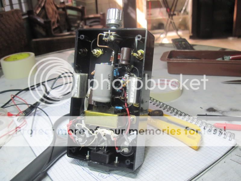
i built this preamp on a plastic casing....the choke is a CM one..
the preamp was very quiet, no hum, no hiss....just music...

- Status
- This old topic is closed. If you want to reopen this topic, contact a moderator using the "Report Post" button.
- Home
- Amplifiers
- Tubes / Valves
- Filter Chokes wired for CMR