Like with series filters, there is very little useful information available at the transient perfect B&O Filler driver concept. At least not in any form that helps me! Perhaps it's all a big secret?
It's obviously difficult to implement in the real world. AFAIK, it can be done with second or fourth order filters. But I've never simmed anything that looks remotely close. Perhaps I messed a trick. B&O used mid and high soft domes with Fs equalisation and time alignment by the look of it. Peerless foamed woofer I believe.
Second order bass and tweeter, and two element mid. That's doable in this more conventional +-+ polarity 3 way:
SEAS Kit 503
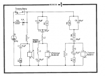
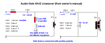
Anyway, here's the B&O circuit as a point of departure. I'm not really sure what I am looking for in a sim either, since mine doesn't output impulse response!
It's obviously difficult to implement in the real world. AFAIK, it can be done with second or fourth order filters. But I've never simmed anything that looks remotely close. Perhaps I messed a trick. B&O used mid and high soft domes with Fs equalisation and time alignment by the look of it. Peerless foamed woofer I believe.
Second order bass and tweeter, and two element mid. That's doable in this more conventional +-+ polarity 3 way:
SEAS Kit 503
Anyway, here's the B&O circuit as a point of departure. I'm not really sure what I am looking for in a sim either, since mine doesn't output impulse response!
Attachments
Like with series filters, there is very little useful information available at the transient perfect B&O Filler driver concept. At least not in any form that helps me! Perhaps it's all a big secret?
It's obviously difficult to implement in the real world. AFAIK, it can be done with second or fourth order filters. But I've never simmed anything that looks remotely close. Perhaps I messed a trick. B&O used mid and high soft domes with Fs equalisation and time alignment by the look of it. Peerless foamed woofer I believe.
Second order bass and tweeter, and two element mid. That's doable in this more conventional +-+ polarity 3 way:
SEAS Kit 503
Anyway, here's the B&O circuit as a point of departure. I'm not really sure what I am looking for in a sim either, since mine doesn't output impulse response!
Oh, wow! Thanks for B&O xo schematic! Really interested in this.
I think that helps a great deal, GM!
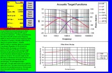
I'm sure our John Kreskovsky won't mind us cutting out the middleman and going straight to his target function image. Below.
This is acoustic slopes, of course. TBH, I always find John hard to read. Is that his fault? NO. I think visually, he thinks abstractly.
The basic theory in algebra (well function of a complex variable to be strictly precise, s is jw where j is complex, w is angular frequency and A is a constant which defines the Q of the filter, I've probably been slack with the +/- signs...
) is you split a transfer function like ss + 2As +1 / ss +2As +1 (=1) into a low pass, a band pass and a high pass.LP= 1 / ss +2As +1 = 12dB/octave second order bass.
BP= 2As / ss +2AS +1 = 6db/octave mid pass midrange.
HP= ss / ss +2As +1 = 12dB/octave high pass tweeter.
Then when you add them a la B&O, you have transient perfect.
Transfer functions can also be expressed as poles and zeroes. It's equivalent. Siegfried Linkwitz thinks this way too.
An externally hosted image should be here but it was not working when we last tested it.
That rather exotic looking thing is a sixth order allpass filter, related to two cascaded 3rd order butterworth filters, which is LR6 as it goes. Pure phase shift and group delay and flat frequency response. Quite realisable with opamps. The poles (infinities) are on the left or the vertical complex axis in the real world, and the zeroes are on the right, or the vertical axis.
Anyway, back to filler drivers and one target response of many below, if I follow. That looks pretty demanding on the mid IMO. It's the phase that is the big target. This reminds me of two way third order butterworth. The polarity that gets the tweeter phase above the bass is theoretically better on transients than the opposite. I can never hear it though. In fact I prefer the sound of the worse one.
Nor could I ever hear an allpass network in circuit with speakers or headphones when I did this 30 years ago. But maybe I didn't know what to listen for.
Attachments
Last edited:
3-way XO Test Bed
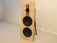
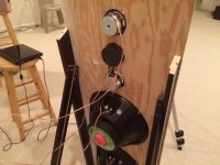
I had some drivers lying around and found some plywood so I decided to make a XO test bed to play around with some of these ideas. Maybe look at the Duelund XO, the B&O filler, etc. For simplicity I made it an OB which will limit bass extension but I am more interested in exploring the stuff above 100Hz to see if I can get transient perfect responses etc.
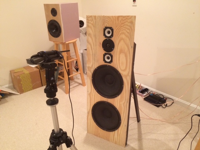
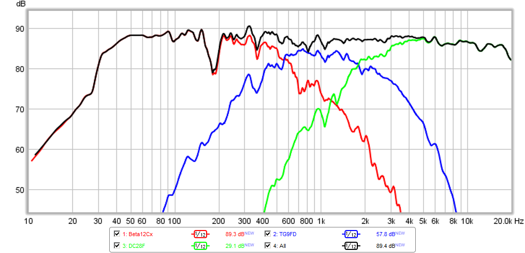
The baffle is 16in wide x 44.5in tall. The drivers are spaced, from the top edge at 5.0in to the mid (TG9FD-10-8) then 4.0in between the mid and tweeter (DC28F-8), then 4.0in from the tweeter to the next mid (TG9FD-10-8), then 8.0in to the woofer (Beta 12cx) and woofers are spaced 13.0in apart. There is a frame on the back and some legs to support it. My plan is to wire the TG9FD's in parallel for 91dB at 2.83v sensitivity, and the Beta 12cx's in parallel for 100dB at 2.83v sensitivity. The DC28F-8 is rated at 89dB at 1W, so probably closer to 91dB at 2.83v. The OB will cut into the woofer efficiency quite a bit but should get me back to circa 90dB after all is said and done?
Here are some photos... have not had time to wire it up yet. Will be running it fully active using 1x4 miniDSP advanced 4-way XO and have option of powering woofers with independent amp channels or in parallel. Should be fun and good for learning about 3-way or evebn 4-way XO's. May not be the best drivers but it was what I have lying around. I think the TG9FD should be ideal for the hole filler as it has a wide bandwidth being a full range capable of 250Hz to 9kHz before breakup.


I had some drivers lying around and found some plywood so I decided to make a XO test bed to play around with some of these ideas. Maybe look at the Duelund XO, the B&O filler, etc. For simplicity I made it an OB which will limit bass extension but I am more interested in exploring the stuff above 100Hz to see if I can get transient perfect responses etc.
The baffle is 16in wide x 44.5in tall. The drivers are spaced, from the top edge at 5.0in to the mid (TG9FD-10-8) then 4.0in between the mid and tweeter (DC28F-8), then 4.0in from the tweeter to the next mid (TG9FD-10-8), then 8.0in to the woofer (Beta 12cx) and woofers are spaced 13.0in apart. There is a frame on the back and some legs to support it. My plan is to wire the TG9FD's in parallel for 91dB at 2.83v sensitivity, and the Beta 12cx's in parallel for 100dB at 2.83v sensitivity. The DC28F-8 is rated at 89dB at 1W, so probably closer to 91dB at 2.83v. The OB will cut into the woofer efficiency quite a bit but should get me back to circa 90dB after all is said and done?
Here are some photos... have not had time to wire it up yet. Will be running it fully active using 1x4 miniDSP advanced 4-way XO and have option of powering woofers with independent amp channels or in parallel. Should be fun and good for learning about 3-way or evebn 4-way XO's. May not be the best drivers but it was what I have lying around. I think the TG9FD should be ideal for the hole filler as it has a wide bandwidth being a full range capable of 250Hz to 9kHz before breakup.
Attachments
What you are doing is flippin' amazing, xrk971!
I REALLY admire your enthusiasm here. That little Peerless mid actually looks like a great advance on the olden days stuff. MAYBE this is doable.
I haven't done the mathematical detail of analogue and digital filters in many years really. But I'll tell you what I know if you allow for mistakes based on inaccurate memory. Remember s (=jw) is a complex variable, so squaring it as in ss changes the sign to -1.
So far we've been looking at the ideal second order ss + 2As +1 / ss + 2As +1 (=1) sort of transfer function.
Phase or allpass networks are actually ss - 2As +1 / ss + 2As +1 (= the unit circle modulus 1). Not transient perfect.
OK, low pass bass LR2 is 1 / ss +2s +1.
High pass tweeter LR2 is ss / ss +2s +1.
Wire them negative polarity and you get ss - 1 / ss + 2s +1.
That is : (s + 1)( s - 1) / (s + 1)(s + 1) = s -1 / s + 1 = a first order allpass phase network with flat frequency response and Duelundish perfect phase alignment. In fact the familiar LR2 12db/octave negative polarity two way speaker:
18W-8434G00
Well, it's missing the bandpass or midrange 2s / ss +2s +1 term. Which is what the filler driver is all about I think. That and John K's remark that the filler driver is a positive polarity solution.
I'm not too sure how your experiment is going to pan out. It may be you get perfect transient response and power response, but not flat frequency or phase alignment here. Sod's law says you can't have it all. For sure you're going to need Fs correction for the exact 12 dB or 6 dB slopes, which does work well IMO. Maybe you'll need to think about time alignment more too.
I am going to go by the filters recommended by the John K spreadsheet. He has the slopes characterized in terms of Q and fc. For the HP, LP, and BP, and based on the overlap factor you want. So rather than going with LR2 or whatever, I will first flatten the drivers natural response as much as possible with some PEQ. Then use the spreadsheet from miniDSP that lets me calculate bi-quad coefficients for a given Q and fc. Then load those into the advanced parametric EQ page. This way, it should then match the slopes prescribed in the spreadsheet for transient perfect.
Although the easy thing to try is an LR2 for bass and tweeter and BW1 for mid. That is the nice thing with miniDSP. Easy and no harm done and no time or money wasted on passive xo wiring.
Although the easy thing to try is an LR2 for bass and tweeter and BW1 for mid. That is the nice thing with miniDSP. Easy and no harm done and no time or money wasted on passive xo wiring.
xrk971, there's many ways to skin a cat!
In terms of the old B&O circuit, I just try and pick out the key elements. I wish I had time right now to work on this myself. LR2 is, broadly speaking, the lowest Q second order filter.
What DOES work well for very exact slopes is Zobel impedance and driver Fs correction. The Audio Note and the KEF acoustic butterworth used it. As does the Elsinore. Get rid of that pesky Fs resonance with a LCR shunt and you get really flat 12dB and 18db/octave slopes.
That's the theory. Troels Gravesen likes it too.
Attachments
Last edited:
XO Test Bed initial trial all LR2
Just to get things going, I setup a conventional LR2 XO centered at 1kHz with the LF having a LPF at 500Hz, and the HF having a HPF at 2000Hz, and the mid with bandpass filters defined by 500Hz and 2000Hz.
Here is the wiring, I went with quad-amplified with 4 channels from two TPA3116D2 amps. Using minDSP 1x4 advanced 4-way plugin for the XO and PEQ.

Here is the speaker setup for measurement at 0.5m
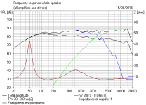
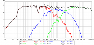
This is measured acoustical XO:
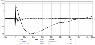
This is the measured impulse response and step response (not transient perfect because this is all LR2) :

This is the harmonic distortion at low power:
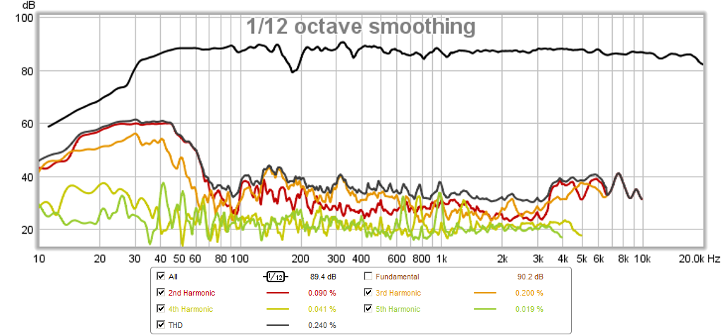
Al in all, it sounds very nice - I am surprised how rich and full the bass is. The -3dB point is about 35Hz. System sensitivity worked out perfectly matched with very minor level adjustment between the drivers. Jazz ensembles have a very good presentation with excellent dynamic range. Vocals and brass instruments sound very convincingly real. Plucked stand up bass is excellent with weight that you can feel. I should note that these Beta12cx's are off spec with a high Qts of 0.65. This may be contributing to the better than average bass extension given the lack of wings even on an OB.
Here are some sound clips of this speaker with the all LR2 XO (change .asc to .mp3 to listen):
Just to get things going, I setup a conventional LR2 XO centered at 1kHz with the LF having a LPF at 500Hz, and the HF having a HPF at 2000Hz, and the mid with bandpass filters defined by 500Hz and 2000Hz.
Here is the wiring, I went with quad-amplified with 4 channels from two TPA3116D2 amps. Using minDSP 1x4 advanced 4-way plugin for the XO and PEQ.
Here is the speaker setup for measurement at 0.5m
This is measured acoustical XO:
This is the measured impulse response and step response (not transient perfect because this is all LR2) :
This is the harmonic distortion at low power:
Al in all, it sounds very nice - I am surprised how rich and full the bass is. The -3dB point is about 35Hz. System sensitivity worked out perfectly matched with very minor level adjustment between the drivers. Jazz ensembles have a very good presentation with excellent dynamic range. Vocals and brass instruments sound very convincingly real. Plucked stand up bass is excellent with weight that you can feel. I should note that these Beta12cx's are off spec with a high Qts of 0.65. This may be contributing to the better than average bass extension given the lack of wings even on an OB.
Here are some sound clips of this speaker with the all LR2 XO (change .asc to .mp3 to listen):
Attachments
-
 hole-filler-lr2-all-hd.png152.6 KB · Views: 1,229
 -
 hole-filler-lr2-all-ir.png58.3 KB · Views: 1,232
 -
 hole-filler-lr2-all-xo.png91.9 KB · Views: 2,839
 -
 xo-test-bed2.JPG88.4 KB · Views: 2,329
 -
 xo-test-bed1.JPG101.6 KB · Views: 1,400
 -
Hole-Filler-clip-1.asc1.8 MB · Views: 71
-
Hole-Filler-clip-2.asc1.7 MB · Views: 64
-
Hole-Filler-clip-3.asc1.7 MB · Views: 63
Last edited:
@ System 7.
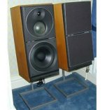
I might be mistaken, but the 3 way B&O you're showing (inc x/o) is not a B&O filler-driver system and which, to my best of knowledge, has never marketed or sold as such. It looks more like the classic 75 mm dome ( Vifa/Seas) 3 ways that were popular in the mid eighties.
Look at the B&O M75 instead, with 4 drivers, which has an 11 cm Peerless cone midwoofer as filler between 30 cm woofer and 50 mm dome.
But then again, I might be mistaken.
Regards,
Eelco
"Pardon my ignorance here, but what actually is a "Filler" driver??"
Patent US4031321 - Loudspeaker systems - Google Patents
It sounds fantastic, much better than a LR24.
Patent US4031321 - Loudspeaker systems - Google Patents
It sounds fantastic, much better than a LR24.
John K's spreadsheet shows different overlap factors that allow a wider "hole" whereas the patent shows the LF and HF driver having a crossover at the same frequency such that a deep hole or null is created. Will the wider hole (less overlap between LF and HF) still yield a transient perfect response?
Following, nice work
What's the dip @ around 200Hz ?
I wonder what 6dB Oct would be like, @ appropiate f's ?
I suspect that might be a cancellation due to front back waves between the two woofers? I could turn one woofer off to see if it goes away. Mic is too close for it to be floor bounce.
"John K's spreadsheet shows different overlap factors that allow a wider "hole" whereas the patent shows the LF and HF driver having a crossover at the same frequency such that a deep hole or null is created. Will the wider hole (less overlap between LF and HF) still yield a transient perfect response? "
A Butterworth 12dB run in phase has an infinite hole, which filler driver fills it perfectly, and will even pass a square wave (see the JEAS for the photos).
A B12 or LR12 sounds poor out-of-phase, has a hole in-phase.
A B18 or C18 sounds poor no matter which way you connect it.
A LR24 sounds good in-phase.
But a B12 in-phase with the filler driver sounds much, much better.
I remember the full line of B&O speakers well, from 1980 or so. They were all marketed as using the filler, and actually didn't sound all that bad. We sold quite a few, and one friend is still using a pair.to my best of knowledge, has never marketed or sold as such.
........the patent shows the LF and HF driver having a crossover at the same frequency such that a deep hole or null is created.
Will the wider hole (less overlap between LF and HF) still yield a transient perfect response?
Yeah, all this has been a bit of a revelation to me as the traditional 'filler driver' dates to at least the late '40s post WWII depression that forced many manufacturers to cut inventory costs, so among other things, Altec started using more, smaller, horns to fill in dips [hence the 'filler' moniker] to maintain/improve overall speech intelligibility in stadium, etc., installs, allowing a reduction in the variety of horn profiles required and of course parts cost reduction through ordering in larger quantities. This also made shifting more production to outside vendors cost effective, so a net cost reduction overall even though more parts/labor was required per install.
Didn't know anyone had patented it either, though not surprised as so much was worked out by the pioneers that most 'inventions' since then have either been basically renewing someone else's old idea/lapsed patent or just a minor tweak to one.
Yes, if properly time/phase aligned, but the wider the gap, the more complex the XO unless the drivers have at least a two octave ~flat BW on either side of the XO point and the more critical its physical placement becomes with increasing 'filler' BW if not all done in the digital domain since it's not so much a 'filler' as a discrete multi-way, in which case you're better off IME to follow the pioneers and make the 'filler' a 'FR' driver and shift the XOs outside our most acute hearing BW, i.e. at least the ~500 - 5 kHz BW and ideally the ~250 - 8 kHz BW.
GM
- Status
- This old topic is closed. If you want to reopen this topic, contact a moderator using the "Report Post" button.
- Home
- Loudspeakers
- Multi-Way
- "Filler" driver ala B&O