Re: as seen on ML 23,5
I guess my philosophy was: even if the design wasn't great, if I make it look nicely I would feel better about it.") It changes now when I get all the info from this forum and form is not as important as it used to be.
It changes now when I get all the info from this forum and form is not as important as it used to be.
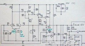
The blue caps are Rifa and the schematic is as follows.
HarryHaller said:Peter great job as usual. You are the Martha Stewart of DIY.
H.H.
I guess my philosophy was: even if the design wasn't great, if I make it look nicely I would feel better about it.
It changes now when I get all the info from this forum and form is not as important as it used to be. The blue caps are Rifa and the schematic is as follows.
Attachments
Fet Regulator debate
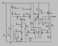
I guess it wouldn't hurt to give a little design background on the regulator circuit.
Vin should be between 24 and 30 volts. Vout is 16.2 V with the feed back resistor values shown be could be set for 12 V to 20 V with enough input voltage. Vin - Vout should be 10 to 15 volts. The circuit could be adapted for negative voltage with p channel devices swapped for N channel and vice versa. An RC filter increases the PSRR for the voltage references and diffamp
LEDs are biased by a constant current diode for 5.4 volt and also Vin - 3.6 volt references. A p channel mosfet provides a current souce for the drain resistor to ground and half the current through the jfet diff pair. Putting the drain resistor to ground instead of Vin provides better PSRR and freedom in baising jfet diff amp for higher drain current and therefor higher gain. It is probably to only thing novel about this circuit.
A p channel fet is used to drive the n channel fet to help offset the gate to source voltage and increase to open loop bandwith.
DC gain is 3 and bypassing the feedback resistor with a cap reduces noise and output inpedance by a factor of three at audio frequencies. The circuit has about 40 dB of negative feedback an could be easily changed for more or less feedback. I have tried to use the pararmeters that make a good preamp circuit for the voltage regulator by paying attention to noise,bandwidth, PSRR, not using too much negative feedback, using all fets and LEDS, and keeping the circuit simple and compact. It is much more fun and tunable than the standard three terminal or op amp based regulator and required little design or construction time. I like using all discretes with no ICs for even the voltage references.
H.H.
Thanks Harry for taking the time and trouble to provide both a schematic and a description of its operation. I think you are perhaps being just a little too modest when you say that the drain to ground is the only novel thing about your circuit.
Sadly I cannot find much to debate, though I would like to know how well it works - preferably in terms of the real world performance of the equipment being powered. I too am building a preamp (along with Aleph-X and various other X like things) and consequently am interested in suitable power supplies. Now if only someone would start back engineering Wayne's secret attenuator...
One question I do have, is why are the gate resistors of apparently arbitrary (and slightly larger than the norm) value? Is it arbitrary or am I just ignorant? Presumably the LEDs were chosen for being quieter than other voltage references (e.g. Zeners). I note too your inclusion of C8, an idea from another thread if I am not mistaken. This has worked well for me in another power supply.
Final question (honest). I note that your regulator derives its reference from the (filtered) input voltage, whereas the ML schematic posted by Peter, takes it from the output. Apart from the need to make sure that the regulator actually starts up with the latter arrangement, is there any other reason to prefer the input arrangement?
Back to the X-SOZ thread now as it seems to have gone a bit stale.
Ian.
You did it to us again!
Once again, you insist on posting in a format some of us ponces cannot open. Why must you be so strident? Probably uses too many parts anyway.
And don't tell him he is being modest, that will only encourage more of his outlandish behaviour.
(The above posting is meant to be gratuitous humour for those of you not aware of Hairy Holler's past actions.)
Jocko
Sadly I cannot find much to debate
Sorry to dissapoint you. Gate resistors chosen for stablity and to protect fets from discharge currents of 0.1uF and 3 uF caps on power down. C8 across feedback resistor I probably saw in the Sulzer regulator article in Audio Amatuer in 1980 I think. I used one current diode (Z> 10 Meg!) to bias both LED voltage references but did use RC filter before references and front end diff amp. This is a little better than a resistor..... I think rejection of input noise may even be more important than low output impedence for regulators for line level circuits. A fairly low voltage for the refence voltage was to help keep drain to source voltages for the jfets and P mosfet current source high enough to lower capacitance and decrease output conductance. The use of a P channel mosfet to drive the output mosfet also allows a greater drain to source voltage to lower capacitance. A lenthy look at the fet data sheets is very enlightening on these details. I also like to isolate device capacitances with resistors to minimize RF funnies from wiring inductance. Thanks for your interest.
H.H.
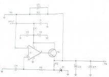
Sulzer regulator
The grandfather of all line level regulators. Michael Sulzer's op amp based regulator from The Audio Amateur 2/1980. A1 can be built from discreet transistors for the op amp phobic. A good simple topology that has been the basis for dozens of designs.
The grandfather of all line level regulators. Michael Sulzer's op amp based regulator from The Audio Amateur 2/1980. A1 can be built from discreet transistors for the op amp phobic. A good simple topology that has been the basis for dozens of designs.
Attachments
Anybody have any opinions on whether these sort of regulators are the way to go for preamp circuits? I'm just wondering whether anything that uses loop feedback, even if in small proportions, is entirely appropriate for a low current class A circuit. Maybe something along the lines of a follower with suitable voltage reference, followed by a capacitor multiplier and RC filtering might be better? Anyone done this sort of comparison? I intend to try myself sometime, but like all such things I must first find some spare time.
Ian.
Ian.
Peter Daniel said:
All my Rifa and Wima caps are surplus, bought locally. I've got quite a selection of Wima MKS 10, 2,2uF/250V. If somebody interested I might spare few at $3.
to have Wima caps have a look to www.farnell.com
Re: Low Noise Power Supply
Harry the MAX6250 was a hint (to better sound). Even if the part is $ 30 it is worth it.
I don' t think the lower noise is a issue. Most noise coming out of the speakers is not due to the powersupply I believe.
As Groman pointed out (volume)pots at the input of the powersupply are a good measure to reduce the noise originating in the line amp of the preamplifier. But back in 1975 Crown had already pots in the inputs. It was my first high power amp.
Correction that must be OP176 datasheet fig. 41.Elso Kwak said:(see OP275 datasheet)
Harry the MAX6250 was a hint (to better sound). Even if the part is $ 30 it is worth it.
I don' t think the lower noise is a issue. Most noise coming out of the speakers is not due to the powersupply I believe.
As Groman pointed out (volume)pots at the input of the powersupply are a good measure to reduce the noise originating in the line amp of the preamplifier. But back in 1975 Crown had already pots in the inputs. It was my first high power amp.
I don' t think the lower noise is a issue
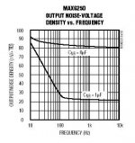
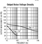
What's the point of a 30 dollar voltage reference then? The supply noise can be responsible for the noise level in a circuit. Particularly for single ended circuits with no feedback. the Pass Pearl phono preamp would be a perfect example. The Maxim MAX 6250 requires a 1 uF noise reduction cap to acheive better noise specs than the LM329. The references are also different in that the 6250 is a series regulator and the LM329 is shunt regulator which is much more flexible in the supply voltages used to bias it. With a J503 current fet biasing it the PSRR is over 120dB at 20 Hz compared to about 90dB for the MAX6250. At any rate most designers would use a low pass filter after the reference leaving the real difference in in parts as the amount of subsonic noise and absolute voltage stability; which are usally not big concerns for audio circuits. I can build a complete low noise regulator for the 20 something dollar diffence in price between the references.
H.H.
P.S. The Linear Technology LT1027DCN8-5 has simular spec to the MAX 6250 and its a 5 dollar part.......
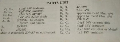
Attachments
Re: Re: Low Noise Power Supply

Elso Kwak said:
Harry the MAX6250 was a hint (to better sound)
The Ultimate reference or Power Supply???
Hi,
Tonight I decided to perform a silly experiment.
My line of reasoning is that a regulated supply never can be better than the reference used in it.
I decided to make a string of six alkaline batteries, size AA, to power the reference (MAX6250) with 8.5V. Such a reference will have infinite PSRR (Power Supply Rejection Ratio) and zero ripple voltage.
When powered up the supply of my preamp worked fine. The reference gave exactly +5V out.
Much to my surprise & disappointment the <B>SOUND</B> was flat and lacking bassslamm.
<B>WEIRD</B>. End of experiment.
- Status
- This old topic is closed. If you want to reopen this topic, contact a moderator using the "Report Post" button.
- Home
- Amplifiers
- Solid State
- Fet regulator circuit