I am having some stability issues with my 5-20 builds. The open loop gain is 1666 and the closed loop gain is 53.7. I am using a fairly large amount of feedback (30db), I am thinking the large amount of feedback is causing the instability and want to lower it and start all over. I would like to use around 20db feedback so my closed loop gain should be 166.
In addition to lowering the amount of feedback I plan to remove the lead compensation cap (C9, currently 330pF) and the lag compensation RC network C1 and R3.
After these modifications I plan to recheck stability and then recalculate and add the compensation networks if need be, hopefully I won't need them. Problem is I do not have access to a dual trace scope so figuring out the break points is going to be impossible so I might have to do it empirically.
Am I on the right track lowering the feedback and starting over? Anybody else build a 5-20 clone and if so how much feedback did you use?
One problem with the stock lag compensation network is using the formula: Clag = 1/(2*pi*f2*Rlag) where f2 is 45 degree break point, Clag is 47pF and Rlag is 4.7k.
.000000000047 = 1/(2*3.14*f2*4700)
f2 = 720,849
Is this right? Seems like most of the 45 degree breakpoints in the example I read were all under 200kHz.
-bird
Attachments
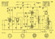
30W Push Pull amplifier designed by Claus Byrith, Royal Academy of Music in Aarhus, Denmark. | Lundahl Transformers
Hi,
Best articles I've ever read about EL84/5-20 related designs.
rgds, sreten.
Hi,
Best articles I've ever read about EL84/5-20 related designs.
rgds, sreten.
Even a single trace scope can help, if the amplitude down to 0.7, you have 45 deg lag. I would plot out the gain vs frequency and plot on a log paper. From the plot, you can look at the slope and break point to find all the poles and zeros. If the gain is too high, you can break up into stages and measure individual stages and then add them up. Problem with the power tube and OT, you need to use the speaker as a load as the speaker present a reactive load and change the poles and zeros.
I think it's the right idea of removing the C9. I don't think the C1 and R3 really work, the break frequency is too high. the pole is C1 and 100K where the poll freq is 1/(2\pi R C)= 1/(6.28 X 100,000 X 47 X 10^(-12))=34KHz, the zero is 1/(2\pi X 4700 X 47 X 10^(-12))=720KHz. This lead lag network is at too high a frequency.
Remove all the compensation to start like you said.
Or remove C9, try increase C1 to say 220p etc to lower the lead lag frequency.
Last edited:
Or remove C9, try increase C1 to say 220p etc to lower the lead lag frequency.
It is what I was going to suggest wile reading, 100pf may be enough.
I recently did a 5-20 with EL84 ,and I had to use an ECC82 at the first stage to keep the open loop gain down and keep the feedback to a manageable level. The closed loop gain with ECC82 is about 600..I ended up with 18db of feedback for .35V RMS sensitivity. Firs breakpoint of my output transformer is at 19Khz, lag is 120p and 3K // 47K anode resistor, Clead is only 10pf // 100 K.
You have to keep in mind that these designs have very high input sensitivity, which was the norm at the time. So when you apply manageable levels for feedback you end up with a super sensitive amplifier.
There is a thread about it in here
You have to keep in mind that these designs have very high input sensitivity, which was the norm at the time. So when you apply manageable levels for feedback you end up with a super sensitive amplifier.
There is a thread about it in here
Last edited:
I used half an ECC81 instead of EF86 for the first stage, and found that no lead-lag network was needed. This is partly because the gain was lower, but also because the HF pole formed by the output resistance of the first stage and the input capacitance of the phase splitter would be at a higher frequency.
I was thinking about this, I think the best way is to open the feed back, use a signal generator to drive the input. Use speaker as the load and measure the output to the speaker and plot the gain vs frequency on a log graph paper. Treat it like taming an opamp. You plot the open loop gain and look at the poles and zeros. Then draw the feedback like. Look at the 0dB loop gain cross over. Then you add compensation as needed to achieve a single pole crossover just like taming an opamp.
I think the lead lag compensation is going to work, just a matter of finding the value by looking at the graph. Try one set of RC value and then listen to it. I have no experience on audio amps, but I did a lot of closed loop feedback control systems. Sometimes you give it too much phase margin, the slew rate and settling time is going to suffer. A lot of times, I kept the loop gain high at the frequency of interest, then using multiple lead lag networks to drop the loop gain very fast, then design the lead to kick in when close to the 0dB crossover to level it to a single pole crossover. My guess is if you play it safe, the sound might not be as good. Sometimes a little peaking can give you the oops for the lack of words!!! .....Now it's just my guessing from the closed loop feedback design!!!
I think the lead lag compensation is going to work, just a matter of finding the value by looking at the graph. Try one set of RC value and then listen to it. I have no experience on audio amps, but I did a lot of closed loop feedback control systems. Sometimes you give it too much phase margin, the slew rate and settling time is going to suffer. A lot of times, I kept the loop gain high at the frequency of interest, then using multiple lead lag networks to drop the loop gain very fast, then design the lead to kick in when close to the 0dB crossover to level it to a single pole crossover. My guess is if you play it safe, the sound might not be as good. Sometimes a little peaking can give you the oops for the lack of words!!!
.....Now it's just my guessing from the closed loop feedback design!!!
Last edited:
The fundamental problem with four stage amps like the 5-20 is that there are bound to be lots of poles and zeros which makes ensuring stability rather hard to do. If you reduce NFB, stability becomes easier but sensitivity increases. These are already sensitive amps so if you do not need the sensitivity the best option is to reduce the open loop gain by removing a stage. This means you need less NFB for a given sensitivity and there are fewer poles and zeros to worry about. It is also worth thinking about reducing poles/zeros by dc coupling stages.
Cheers
Ian
Cheers
Ian
I have tweaked a number of these designs, and found some simple trial and error works really well.
C9 has never helped my designs, from ST70 clones to 5-20's from scratch. Remove it, at least for now.
R13 to whatever you want it to be. 20dB of feedback is a good starting point if your transformers are decent.
R3-C1 in my experience make a huge difference in sound quality and scope trace, and is one of the cases where what you see on the scope really does line up with the ears. I strongly recommend borrowing a scope from someone on this forum; perhaps they live 25 miles away and are willing to assist you.
Set R3 to 10% of R6. C1 is adjusted for nice looking 1 kHz rising edges. You want it as steep/fast as possible with minimal/no overshoot and ringing. Perhaps you could even do this by ear, but it would be maddening in my opinion. Beg you to borrow a scope or phone a friend.
When you follow this procedure, it easily becomes apparent when you need to increase or decrease R3. You will be able to see if varying values of C1 make no real change in scope trace, R3 needs to be decreased in value. I have a bin of cheap micas I use for swapping in C1 until I find the right size.
Last edited:
Following on what DF96 said, if you don't want to replance the EF86 with a triode, an easy dodge would be to remove C3. This will lower the gain of the EF86 to around 50 or so. This will probably halve your open loop gain, so you can then apply around 20dB of feedback and still get the same sensitivity that you have now.
Have you measeured the open loop bw at the speaker terminal? Not only a -3dB point but also the shape of curve.
Larger is this parameter less you have the issue on stability; but this means the trafo is good enough.
It is a good idea to check the bw of each stage also on anodes of power tubes (primary of trafo), always in open loop; In this way you can have a right idea if the active stages are well implemented.
Maybe a good solution is to replace a EF86 with a Srpp of 6922; in this way you get on first stage a gain of 20 with a reasonable low distortion and you can mantain the direct coupling with IInd stage that is driven ( in this case) by a reasonable low impedance.
Walter
Following on what DF96 said, if you don't want to replance the EF86 with a triode, an easy dodge would be to remove C3. This will lower the gain of the EF86 to around 50 or so. This will probably halve your open loop gain, so you can then apply around 20dB of feedback and still get the same sensitivity that you have now.
This is the part of the circuit that I was looking at. Changing R4, R5, and C3 will allow you to manipulate the loop gain. You can scale R13 and C9 accordingly.
I have done many back of the envelope stability calculations that went out the window at prototype time. Many times have I determined compensation empirically.
Have you measeured the open loop bw at the speaker terminal? Not only a -3dB point but also the shape of curve.
Walter
Yes, this is what I suggested also, plot it on a log graph paper with closer points to see the slope more accurately and to point out where the gain drop at -20dB/dec or -40dB/dec.....hopefully not -60dB/dec!!!
Lowering the NFB not necessary make it more stable, it all depends on the the 0dB crossover. A lot of open loop gain has -40dB/dec roll off at higher open loop gain portion, then compensate to -20dB/dec at lower open loop gain for stability. You reduce NFB ( raise the close loop gain), you might bring the 0dB crossover at the -40dB slope and the amp oscillates.
This is just performing the standard Bode plot. With the open loop gain plotted, you can add lead lag compensation to ensure a single pole 0dB crossover. Bode plot never failed me yet, it's simple and fast to plot. Then you can design the compensation to tailor for best sound.
Last edited:
Vitally important :-Don't remove C1 R3, these determine the pole at HF 60KHz ultrasonic upward end. Omit these components and If your o/p tubes are glowing red for no reason, then the amp is behaving as a good oscillator and lost it's HF pole. The other thing is one may not hear it, only a bit of PSU hum as the PSU suffers.
A others mentioned, a low power lookup with output viewed on a scope to determine square wave overshoot and adjust C1/R3 for best shape..The problem for many is that the global feedback components also interact, generally I test without that GNFB cap connected at 1Khz, but je more powerful the amp is I often fit a dummy value to "shut it up".. With vintage o/p trannies, I start with several hundred pF for C1, working down often in tango with a 100K pot for R3. I fit that "step response" cap on the GNFB to trim the final response of the completed amp vs load impedance. The priority is that first stage Zobel. Don't omit it.
Remember, many amps of the period era had no GNFB cap fitted. There is an article in the Radiotron handbook. Shall dig it out.
richy
Last edited:
I would plot out the gain vs frequency and plot on a log paper.
This I plan to do after I make adjustments to the circuit. I know it won't be that accurate but it should work ok for my purposes.
I recently did a 5-20 with EL84 ,and I had to use an ECC82 at the first stage to keep the open loop gain down and keep the feedback to a manageable level.
I used half an ECC81 instead of EF86 for the first stage, and found that no lead-lag network was needed. This is partly because the gain was lower, but also because the HF pole formed by the output resistance of the first stage and the input capacitance of the phase splitter would be at a higher frequency.
The fundamental problem with four stage amps like the 5-20 is that there are bound to be lots of poles and zeros which makes ensuring stability rather hard to do. If you reduce NFB, stability becomes easier but sensitivity increases. These are already sensitive amps so if you do not need the sensitivity the best option is to reduce the open loop gain by removing a stage. This means you need less NFB for a given sensitivity and there are fewer poles and zeros to worry about. It is also worth thinking about reducing poles/zeros by dc coupling stages.
if you don't want to replance the EF86 with a triode, an easy dodge would be to remove C3. This will lower the gain of the EF86 to around 50 or so. This will probably halve your open loop gain, so you can then apply around 20dB of feedback and still get the same sensitivity that you have now.
Yes, in short I do want to reduce open loop gain and lower the amount GNFB. I would like to keep the input sensitivity somewhat high because I use a passive preamp. I would also like to keep the direct coupling between first stage and PI and still use the EF86 if at all possible.
So how about triode strapping the EF86? I would be inclined to try EF86 triode if removing the bypass cap isn't enough, maybe do both but I have not looked at the numbers yet.
First things first adjust the open loop gain by removing the EF86 bypass cap and or triode strap the EF86, then lower the GNFB to around 20db. After this I will either try and find somebody in my area with a good scope to help me with compensation network or just plot on a log graph the gain vs frequency myself.
Last edited:
Yes, that is a popular mod. However, you may find the gain is then too low. Also, the degenerated pentode will have less Miller capacitance and much lower distortion than when triode strapped (but higher output resistance, obviously).So how about triode strapping the EF86?
This I plan to do after I make adjustments to the circuit. I know it won't be that accurate but it should work ok for my purposes.
It would be better not to put in any compensation, open the NFB and just plot out the open loop response before putting any compensation in. If you put in the C1 and R3, your plot will include the effect of those. The last thing you want is to create a problem by C1 and R3, then you need to put more compensation for that.
Remove all compensations, plot the graph, then put in poles and zeros to stabilize the amp. If you open the NFB, you should not get oscillation, then plot the graph.
Last edited:
It would be better not to put in any compensation, open the NFB and just plot out the open loop response before putting any compensation in. If you put in the C1 and R3, your plot will include the effect of those. The last thing you want is to create a problem by C1 and R3, then you need to put more compensation for that.
Remove all compensations, plot the graph, then put in poles and zeros to stabilize the amp. If you open the NFB, you should not get oscillation, then plot the graph.
The adjustments I am doing before plotting is to lower open loop gain to compensate for less GNFB.
How about consulting a text on the subject of stability and compensation?
I suggest Sergio Franco, "Design with Operational Amplifiers and Analog Integrated Circuits", McGrawHill. Chapter 8 covers frequency compensation. Granted, it's an op-amp text, but the concepts of feedback, stability, compensation, etc. are the same. The most recent edition (3rd) is pretty expensive, but a 2nd edition can be had for $20-30 on the used market.
~Tom
- Status
- This old topic is closed. If you want to reopen this topic, contact a moderator using the "Report Post" button.
- Home
- Amplifiers
- Tubes / Valves
- Feedback lead/lag compensation