DF96,
you regard an output Tx as a linear device?
If this is the case why use negative feed back to make the amp "more linear" and reduce distortion.
I agree that under DC conditions resistors caps etc may be linear.
However resistors have an inductive element. A pi filter is linear? linear to what? frequency pass, equal attenuation across all frequencies. A tube is regarded as non linear. even though its response is repeatable.
Regards
M. Gregg
Last edited:
Yes distortion goes down, however what effect does the feedback have on the original signal.
None. The Vin term appears throughout the system, indicating that the original signal is always present. Distortion is added in this particular system. (This need not always be the case; a log or exponential converter circuit might multiply instead. Such circuits, fortunately, are not used for linear amplification.)
There is canceling of harmonics in this process.
I do not know what this statement means. Please define. Harmonics do not cancel anywhere in my analysis.
As others have said no NFB seems to "sound better" than systems with NFB. There is something "missing" between the two.
It's well known that tubophiles prefer low-order distortion. This, as well as perception in general, is a psychological effect, and can be adjusted for with double-blind tests... which audiophiles are suspiciously reluctant to undertake.
I don't know why. I don't have any problem with admitting my suggestability, my preference for seemingly undesirable characteristics (in many things besides audio), etc. Perhaps audiophiles are not emotionally secure enough to admit their faults. I don't know.
The feedback is normally through a capacitor and resistor network. These are as you say non linear.
I SAID NO SUCH THING. Please do NOT put words in my mouth which are blatantly in error.
Resistance and capacitance are perfectly linear. You will never, ever see harmonics produced by them. Whether analyzed with differential equations or Laplace equivalents, a sinusoidal input will ALWAYS result in a sinusoidal output. You will never see harmonic terms produced. Phase shift and gain are properties of a linear system.
I would prefer the term "frequency selective" or frequency dependant. There is a phase shift across a capacitor (in simple terms, that’s how a single phase motor uses a run winding).
Actually, it's how it uses a start winding, but nevermind that.
Agreed the phase shift is in place for the feedback and the signal, however the signal sees it once. the feedback sees it twice. The rise time of any signal will be shifted at each stage.
Well, no, the feedback signal is phase shifted exactly as much as the output, because it is derived from the output.
The analysis for a time-dependent, linear system is noticably easier. We can use Laplace analysis here. Since the system is linear, we won't observe distortion or its reduction, but we will see the frequency response.
Example: a differential amplifier with transfer function G = k / (s + a). This is a first order low pass amplifier with passband gain k/a and cutoff frequency a (in rad/s). If we put it inside a feedback loop, we apply the familiar T = G / (1 + G*H) feedback equation, and get:
T = [k / (s + a)] / [1 + k*H / (s + a)]
= [k / (s + a)] / [(s + a + k*H) / (s + a)]
= k / (s + a + k*H)
The resulting system is still first order. In fact, not only is it first order, the pole has moved to a higher frequency, from a to a + k*H! However, DC gain has dropped proportionally, to k / (a + k*H).
Because the system is still first order, there is no "delay", no phase shift, and no error. In fact, at a given frequency, phase shift is smaller than it was before applying feedback!
If we analyze a two-component system, where we have a first-order "plant", which we might consider the load (let's say, the OPT), and a first-order "compensator", which is our amplifier and feedback circuit, we will obtain a second order system. Second order systems are very useful, because by varying the damping factor, rise time, overshoot and stability can be varied directly. As long as stability is maintained, the same general result still applies -- applying feedback widens the bandwidth and reduces phase shift.
Tim
I think with coupling caps and DC, caps are as non-linear as it gets since they block the flow.I agree that under DC conditions resistors caps etc may be linear.
I may be able to illustrate how there is no time delay through these phase shifting components. Lets use a transformer so the vision of capacitance can be eliminated.
If we use a good transformer with a FR below 20hz and we apply a 20Hz signal, the phase shift of 180 degrees would be a delay of 1/2 of the frequency or 1/40 of a second. Now apply the signal and scope both sides and you will see that it does NOT take 1/40 of a second for the signal to appear at the output.
This is what you are seeing!
O.k we have to assume amplitude is the same and both waveforms are voltage.
This is just a quick pic for discussion.
The arrow shows the out of phase. Does it show time lag?
Regards
M. Gregg
The capacitor integrates the current to get the voltage. It just so happens that the integral of a sine wave is ... a cosine wave. And, a cosine wave is identical to a sine wave but shifted 90 degrees. So, because it so happens that with a sine wave the integral also looks like a sine wave, it just looks like a delay.
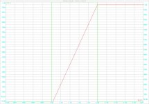
You can see that there is no delay as such if you realise that any change in the input wave also has a change in output wave at the same moment. See the attached graph from a DC current (green) into a cap. When the current is switched on at T=1, the cap voltage (red) *immediately* changes (starts to rise), so there is NO delay (the red curve should start at T=1, the small error is due to the graphing software).
Edit: The integration action is also clear: a constant current causes a linearly increasing voltage...
jan didden
Attachments
Last edited:
I think with coupling caps and DC, caps are as non-linear as it gets since they block the flow.
*Angry sigh*
Please go to school and read a few textbooks.
Blocking DC is a linear operation. Please, all of you, verify the actual definition of linearity before spouting what you think linearity is.
I may be able to illustrate how there is no time delay through these phase shifting components. Lets use a transformer so the vision of capacitance can be eliminated.
If we use a good transformer with a FR below 20hz and we apply a 20Hz signal, the phase shift of 180 degrees would be a delay of 1/2 of the frequency or 1/40 of a second. Now apply the signal and scope both sides and you will see that it does NOT take 1/40 of a second for the signal to appear at the output.
That's a very roundabout way to say it. Far simpler to state, inversion does not have a time-dependent response.
Interestingly, this is only true of 0 and 180 degree phase shifts (modulo 360).
Tim
I think with coupling caps and DC, caps are as non-linear as it gets since they block the flow.
[snip].
No, they are not non-linear because they block DC. There is a continuum from hi freq through low freq to zero freq (DC). At all times, the cap impedance is depending on f and the cap value. That is perfectly linear.
CapImpedance = 1/(2*pi*f*C). Also in the limiting case when f goes to zero, where CapImpedance goes to infinity. All perfectly linear.
jan didden
The apparent phase "shift" through the transformer is not a shift of any kind. It is simply an inversion. Hook up your scope probes, or the primary, backwards and you'll find you're back at zero degrees...
The only true phase shift in the transformer you'll measure is going to be a fraction of a degree at that frequency.
Take a transformer with 5mH leakage inductance (as seen from the primary), 2.5k primary impedance, 8 ohm secondary impedance with 8 ohm load.
At 20Hz, the leakage inductance has a reactance, XL, which is 1.25j (1.25ohms inductive). The small capacitance of the transformer has negligible effect and will be omitted.
1.25j ohms with 2500 ohms gives 0.029° phase shift: ATAN(1.25/2500) = 0.029°
The time delay is 4µs in this case.
If you look at the inverted output then it looks like 180.029°.
No, they are not non-linear because they block DC. There is a continuum from hi freq through low freq to zero freq (DC).
OK. I can see that. For sure. By definition, the cap is linear at DC because it does block the flow.
OK. I can see that. For sure. By definition, the cap is linear at DC because it does block the flow.
No this is incorrect. The definition of 'linear' is different and has nothing to do with blocking anything or not. To a first order, it means that when the frequency doubles, the impedance halves. Or, when the capacitance is halved for the same frequency, the impedance doubles. Linearly. It's easy to see that with the equation for impedance, when freq goes down to zero, impedance goes to infinity but all in linear fashion.
jan didden
At such lo frequency leakage (serie) inductance is peanuts !
Primary inductance coming in parallel with the load is not negligible.
PP transformers reach 100H easily while best SE difficultly exceeds 30H.
More important, this value varies with iron excitation that is (simplifiying) dependent of power output and its effects are also dependent of the internal impedance of the generator know as the tube's Rp . . .wich itself can be tailored by FB loop.
Looping the loop
Yves.
when freq goes down to zero, impedance goes to infinity but all in linear fashion.
I think you are saying the same thing we are. When DC is applied the frequency is 0 and the effective impedance of the cap is infinite.
Blocking flow is really a misnomer and a very short-sighted way to think of what a capacitor really does. It also has nothing to do with linearity.
If you got current to flow through a capacitor (some net amount disregarding leakage), then you'd have exceeded the breakdown voltage of the capacitor. All the capacitor can do is store charge. This points to why the capacitor opposes changes in voltage across its terminals. Any change in voltage attempts to change the amount of charge on the capacitor's plates. Since changing the amount of charge requires current based on the rate of change of voltage, faster rates of change require more current. This current is never flowing through the capacitor though; only into or back out of it.
It would be more logical to say that the capacitor smoothly varies in impedance to effect a change in signal level if used with a signal source of some finite impedance (as all are).
We are not going to get very far discussing feedback if people are unclear what is meant by "linear". It would be like trying to run a marathon before you have mastered walking on two legs. No, a real OPT is not linear but at some frequencies it may be a closer approximation to linear than a valve.
The easy answer is to send all the doubters away to read some textbooks. When they have understood them, they can come back and raise queries about things which puzzle them or things they disagree with. Not likely to happen, but how far should we go in attempting to remotely teach basic electronics and signals?
A capacitor is linear at all frequencies because if you add two different stimuli to it the output is exactly the sum of doing the two stimuli separately. That is what linear means - put twice as much in and twice as much comes out - no more, no less. Valves are nonlinear because this is not true for them, although they are approximately linear for small enough signals. Feedback networks are linear because they are made of linear components like capacitors and resistors. That is why we can use feedback to improve linearity.
Sch3mat1c,
I find your input very informative. However the run start winding was a bit personal. You never make a comment off the cuff then think O.K. it's the run winding. Most will let that go! I was obviously wrong. As I always say I like to learn! My miss quote of some your post was not meant personal even if taken as such.
Regards
M. Gregg
I think you are saying the same thing we are. When DC is applied the frequency is 0 and the effective impedance of the cap is infinite.
Yes.
[snip]A capacitor is linear at all frequencies because if you add two different stimuli to it the output is exactly the sum of doing the two stimuli separately. That is what linear means - put twice as much in and twice as much comes out - no more, no less. Valves are nonlinear because this is not true for them, although they are approximately linear for small enough signals. Feedback networks are linear because they are made of linear components like capacitors and resistors. That is why we can use feedback to improve linearity.
+1
jan didden
*Angry sigh*
Please go to school and read a few textbooks.
Blocking DC is a linear operation. Please, all of you, verify the actual definition of linearity before spouting what you think linearity is.
My original point about blocking DC was mostly philosophical.
If you were to discuss this philosophically, it could be argued that an open wire is also linear. But you would never say something like that because nothing is getting done. An open wire also blocks AC, so is it still a linear device? Just playing...
Philosophically, an open wire is an infinite resistance. According to Ohm's law, any voltage across an infinite resistance carries a current of zero amps. Still linear ....
jan didden
That is what linear means - put twice as much in and twice as much comes out - no more, no less. V.
DF... you've been posting some spot-on stuff. This statement would imply that a cap is only a linear device when installed and used correctly. Since a filter cap can pass a signal by 100% depending on the frequency and then also begin attenuating a signal depending on the frequency, a cap is not a true 2 in and 2 out device under all circumstances.
- Status
- This old topic is closed. If you want to reopen this topic, contact a moderator using the "Report Post" button.
- Home
- Member Areas
- The Lounge
- Feedback Delay Time