Hi Bob,
I do not think so. Maybe it is a result of my poor English. What I mean is that even if I measure very low overall THD (like 0.003%, e.g.), I do not recommend a situation when 5th and higher harmonics have higher amplitude than 2nd or 3rd harmonic. In other words, I prefer decaying amplitude of spectral components (with frequency) even if the resulting THD is very low. I do not like to see 2nd harmonic of -118dB and 5th harmonic of -105dB, as an example. That is what I intended to say, probably I was not very clear.
Regards,
Would this be an example?? (below) It is a standard design goal.
")
More so than just PPM ... even.
OS
Attachments
OS and Dadod,
Which design parameters have the most influence for this type of decay?
Specifically is it dominated by the open loop distortions or rather by the loop gain?
Thanks
-Antonio
In my opinion it is low OLG. Here is another amp with different configuration but very similar OLG.
Attachments
yes I suspect the "harmonic structure" argument is a backdoor way of calling for "flat open loop gain"
but I really don't see where the psychoacoustic support for the idea could come from - after all balanced outputs can have even order cancellation - violating the pattern by suppressing 2nd to below 3rd
I think the stronger argument for weighting higher order distortions as worse is the more complicated IMD spectra with higher energy than similar magnitude lower order nonlinearities - particularly the "down converted" IMD products that aren't masked as well, fall in our higher sensitivity low KHz frequency range
but as Bob just pointed out high loop gain at audio frequencies does suppress the IMD products falling in the region of high gain - so a sloping gain over audio frequencies that gvies 20-40 dB more suppression of the IMD products from higher order nonlinearites at low KHz vs flat gain seems likely preferable despite 2nd, and 3rds being suppressed
Last edited:
but as Bob just pointed out high loop gain at audio frequencies does suppress the IMD products falling in the region of high gain -
Not at all...
IMD products at 1KHZ consequents to a a 19+20khz input signal willnot be reduced by the higher OLG gain at 1khz.
To reduce this undesirable product, you ll have to increase the OLG at 20khz...
Jan,
global feedback needs excess gain for its function that costs bandwidth.
This is so untrue it is not even wrong! Global feedback INCREASES the bandwidth, as in *causes the bandwidth to increase* like * makes a wider bandwidth*.
jan didden
Which design parameters have the most influence for this type of decay?
Specifically is it dominated by the open loop distortions or rather by the loop gain?
That plot was one with 60db OLG, single ended LTP and push pull VAS ... another with the most extreme example similar to this is the "littlefish amp"
A HiFi Power Amp
It also has a similar spectra (single ltp - comp. VAS) BUT, with much higher OLG (110+db) and lower THD.
I am not sure of the exact mechanism , but these amps also "hold" very low thd out to 100k+ instead of the sharper rise at or just above the audio spectrum.
OS
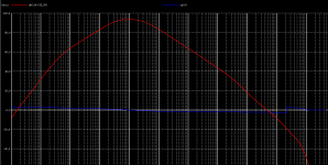
THD vs Gain
Yes, I haven't found yet another way to push it to the limit ...
1) OL 90db gain THD
2) Closed loop THD
3) FB profile
OS
I would suspect that the low THD out to HF is primarily due to two reasons.
Low open loop distortion to start with
High loop gain.
How much feedback have you got at 100khz?
Yes, I haven't found yet another way to push it to the limit ...
1) OL 90db gain THD
2) Closed loop THD
3) FB profile
Attachments
Jan,
The bandwidth is increased by the closed-loop, but the relevant comparison is to be made to the open-loop circuit with the same gain. Again, producing the necessary excess gain gives lower bandwidth, capacitances added for stability will further reduce it. Bandwidth is a distinguishing factor for amplifiers, THD is not.This is so untrue it is not even wrong! Global feedback INCREASES the bandwidth, as in *causes the bandwidth to increase* like * makes a wider bandwidth*.
No. The suppression of unwanted outputs at any frequency is determined by the loop gain at that frequency.wahab said:Not at all...
IMD products at 1KHZ consequents to a a 19+20khz input signal willnot be reduced by the higher OLG gain at 1khz.
To reduce this undesirable product, you ll have to increase the OLG at 20khz..
There are two ways of thinking about feedback. Straightening the transfer characteristic, or suppressing frequency components. The former is only valid for flat open loop gain. The latter works for flat or frequency-dependent gain. NFB suppresses anything which is not in the input signal, including components generated by the mixing caused by NFB. The degree of suppression depends on gain at that frequency, not the frequency of whatever originally created the component.
No. I'm not quite sure where to begin in unravelling your misconceptions, so I won't attempt it.WuYit said:The bandwidth is increased by the closed-loop, but the relevant comparison is to be made to the open-loop circuit with the same gain. Again, producing the necessary excess gain gives lower bandwidth, capacitances added for stability will further reduce it. Bandwidth is a distinguishing factor for amplifiers, THD is not.
DF96,
the term electron mobility (and a number of subterms for carrier velocity) is used in an unequivocal sense in electronics and in the semiconductor branch, please accept it.
It is troublesome for electrons to travel through capacitances, but that`s not all. Electrons are more mobile than holes, electron mobility is considerably higher in valves than in solid state devices and deteriorates with increasing power rating / handling.
OK, the dynamic range lies between a noise level and some level av distortion, anyway, it is compressed in closed-loop amplifiers.
It is troublesome for electrons to travel through capacitances
Indeed.
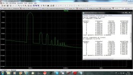
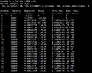
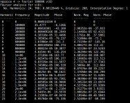
Been working on a quite simple amplifier for a period.. the circuit seems to cancel all higher order distortions... OL-bandwith is 3db at 20 KHz open loop gain is 72 dB.. distortioan at 1KHz +-5V is respectable low:
armonic Frequency Fourier Normalized Phase Normalized
Number [Hz] Component Component [degree] Phase [deg]
1 1.000e+03 3.915e+00 1.000e+00 -5.59° 0.00°
2 2.000e+03 5.113e-03 1.306e-03 66.77° 72.37°
3 3.000e+03 7.762e-06 1.983e-06 -150.42° -144.83°
4 4.000e+03 1.509e-05 3.854e-06 -113.70° -108.10°
5 5.000e+03 3.552e-06 9.071e-07 -47.56° -41.96°
6 6.000e+03 2.674e-06 6.829e-07 -178.23° -172.64°
7 7.000e+03 2.405e-06 6.142e-07 -146.73° -141.14°
8 8.000e+03 1.702e-06 4.347e-07 169.37° 174.97°
9 9.000e+03 2.358e-06 6.022e-07 -150.68° -145.08°
Total Harmonic Distortion: 0.130606%
Note that the sole contribution tor the distortion is 2.order.. others are suppressed by a factor of more than 1000.
and with gain set at 30 dB it retains this distortion profile, but at vanishing low levels..
The amp slews at 70V/us...and totally stable into any Resistance/capacitance one can imagine...
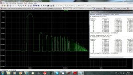
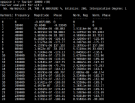
Here is the result at 100 KHz with +-15V output swing...
Harmonic Frequency Fourier Normalized Phase Normalized
Number [Hz] Component Component [degree] Phase [deg]
1 1.000e+05 1.329e+01 1.000e+00 -10.14° 0.00°
2 2.000e+05 1.029e-03 7.741e-05 51.56° 61.71°
3 3.000e+05 7.034e-04 5.293e-05 -102.12° -91.97°
4 4.000e+05 2.454e-04 1.847e-05 22.46° 32.61°
5 5.000e+05 1.696e-04 1.276e-05 -87.87° -77.72°
6 6.000e+05 1.353e-04 1.018e-05 6.08° 16.23°
7 7.000e+05 6.038e-05 4.544e-06 -25.52° -15.38°
8 8.000e+05 6.140e-05 4.621e-06 -13.56° -3.42°
9 9.000e+05 5.151e-05 3.876e-06 -17.48° -7.34°
Total Harmonic Distortion: 0.009725%
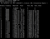
Now to the build....)
armonic Frequency Fourier Normalized Phase Normalized
Number [Hz] Component Component [degree] Phase [deg]
1 1.000e+03 3.915e+00 1.000e+00 -5.59° 0.00°
2 2.000e+03 5.113e-03 1.306e-03 66.77° 72.37°
3 3.000e+03 7.762e-06 1.983e-06 -150.42° -144.83°
4 4.000e+03 1.509e-05 3.854e-06 -113.70° -108.10°
5 5.000e+03 3.552e-06 9.071e-07 -47.56° -41.96°
6 6.000e+03 2.674e-06 6.829e-07 -178.23° -172.64°
7 7.000e+03 2.405e-06 6.142e-07 -146.73° -141.14°
8 8.000e+03 1.702e-06 4.347e-07 169.37° 174.97°
9 9.000e+03 2.358e-06 6.022e-07 -150.68° -145.08°
Total Harmonic Distortion: 0.130606%
Note that the sole contribution tor the distortion is 2.order.. others are suppressed by a factor of more than 1000.
and with gain set at 30 dB it retains this distortion profile, but at vanishing low levels..
The amp slews at 70V/us...and totally stable into any Resistance/capacitance one can imagine...
Here is the result at 100 KHz with +-15V output swing...
Harmonic Frequency Fourier Normalized Phase Normalized
Number [Hz] Component Component [degree] Phase [deg]
1 1.000e+05 1.329e+01 1.000e+00 -10.14° 0.00°
2 2.000e+05 1.029e-03 7.741e-05 51.56° 61.71°
3 3.000e+05 7.034e-04 5.293e-05 -102.12° -91.97°
4 4.000e+05 2.454e-04 1.847e-05 22.46° 32.61°
5 5.000e+05 1.696e-04 1.276e-05 -87.87° -77.72°
6 6.000e+05 1.353e-04 1.018e-05 6.08° 16.23°
7 7.000e+05 6.038e-05 4.544e-06 -25.52° -15.38°
8 8.000e+05 6.140e-05 4.621e-06 -13.56° -3.42°
9 9.000e+05 5.151e-05 3.876e-06 -17.48° -7.34°
Total Harmonic Distortion: 0.009725%
Now to the build....
)Hi Bob,
I do not think so. Maybe it is a result of my poor English. What I mean is that even if I measure very low overall THD (like 0.003%, e.g.), I do not recommend a situation when 5th and higher harmonics have higher amplitude than 2nd or 3rd harmonic. In other words, I prefer decaying amplitude of spectral components (with frequency) even if the resulting THD is very low. I do not like to see 2nd harmonic of -118dB and 5th harmonic of -105dB, as an example. That is what I intended to say, probably I was not very clear.
Regards,
Hi Pavel,
I think I understood you correctly, and I must disagree.
First of all, we should not talk about "low overall THD" without consideration of the amplitude of the spectral components that create that amount of THD, at least not in this conversation. If you say for a given low overall THD it is bad if the 5th order is greater than the 2nd and 3rd order, then I agree with you, since this implies that the absolute magnitude of the 5th order is high. If you must have a given amount of THD, it is better that it be low order.
HOWEVER, if you take a situation where the magnitude of the 5th order is given (fixed), then I believe that lower second order is perfectly fine and probably better.
In your example, amplifier A has 2nd = -118 dB and 5th has -105 dB
Let amplifier B have 2nd = -100 dB and 5th = -105 dB.
Amplifier B is NOT better than amplifier A simply because it has decaying amplitude of harmonics with frequency (UNLESS you subscribe to the distortion masking theory).
Cheers,
Bob
Tunneling should do it, but fortunately tunneling is rarely invoked as an explanation in audio circles.WuYit said:It is troublesome for electrons to travel through capacitances
- Status
- This old topic is closed. If you want to reopen this topic, contact a moderator using the "Report Post" button.
- Home
- Amplifiers
- Solid State
- Feedback affects Soundstage, Imaging, Transients ?