what exactly is the mechanisms behind inter modulation...distortions...??
seems to get quite different results with two tone analysis.. and amplifiers that are good in terms of low distortion also at high amplitudes does not really give the best IMD figures...And for sure the IMD is vastly higher than the normally measured distortions...Eg the Fetsilla with 19-20KHZ test tone has an IMD 1KHz tone at app 2%... and my own design which boasts a 100 times lower distortion and traditionally much better distortion profile has a whooping 4.7%
could be that IMD is the key....as it seems to be significantly higher distortion levels present in multi frequency signals than in single tone steady state...ques that this is a much better measure for what is going on when the amplifier deals with more complex music signals..
The best of my amplifiers boasts an IMD of just 0.7%...compared to single tone distortion of 0.00006% at the same levels..and the goldmund clone that was worked on in this forum is at app 0.8 %...also with very low single tone distortion...
I did an experiment with diodes in output stage making it none switching,,, while the distortion dropped a magnitude the IMD shot up to more than 5 %
Hmmm puzzeled...
Last edited:
IMD is caused by non-linearity, the same source as harmonic distortion. Non-linearity causes signal components to be multiplied together. Trigonometry then gives sum and difference frequencies. Other things being equal IMD and harmonics would be at the same level, but others things are not equal.
'Not equal' things are frequency-dependent forward gain, frequency-dependent feedback and local decoupling. As a result IMD can be larger or smaller than the accompanying harmonics.
'Not equal' things are frequency-dependent forward gain, frequency-dependent feedback and local decoupling. As a result IMD can be larger or smaller than the accompanying harmonics.
Member
Joined 2009
Paid Member
As far as I have understood, IMD is the real curse because it scales rapidly with the signal and signal complexity. It gets less attention here because it's hard to model whereas simple harmonic distortion of sine waves is easy to model and talk about. And IMD products are not only possible from the signal but also from the signal + power supply noise and you have to worry about what happens inside non-linear power supply rail capacitors. It's all too much for me, I just don't think about IMD.
in my sim I have only one nonlinear mechanism to cleanly illustrate the point - the 29 dB reduction in 1KHz IMD with 30 dB added loop gain at 1 KHz is not just a coincidence
in a full amp sim there are many things going on at once - WuYit's 1st sim only gives 8 dB reduction in 1KHz IMD with 18 dB added loop gain at 20 KHz - it appears that this is a less effective approach, with a less "clean" explanation
TMC loop gain should be measured "inside" both of the feedback loops around the output to "explain" distortion reduction - particularly when the output stage distortion dominates
I've pointed out "proper" TMC loop gain measurement, close equivalence of TMC, TPC, and erroneous TMC outer loop measurement false stability margin indication
http://www.diyaudio.com/forums/soli...lls-power-amplifier-book-134.html#post2420438
http://www.diyaudio.com/forums/soli...lls-power-amplifier-book-144.html#post2445393
the time domain analysis of feedback can be valid - but there is are reasons why "Classical Control" texts mainly use frequency domain tools
http://www.diyaudio.com/forums/soli...lls-power-amplifier-book-127.html#post2416770 and my next post a few below
Last edited:
in my sim I have only one nonlinear mechanism to cleanly illustrate the point - the 29 dB reduction in 1KHz IMD with 30 dB added loop gain at 1 KHz is not just a coincidence......
Please correct me if I'm not making any sense...... Since the IMD product, that 1KHz, is something non-existing at the cable side base of the input pair, the NFB mechanism would try not to produce it at the output. Since you have then increased the loop gain at 1KHz by 30db, you've got 30db more NFB at that frequency as your close-loop gain remained un-changed, therefore 30db more suppression to the IMD product, or in your case a 29db reduction which is close enough.
Please correct me if I'm not making any sense...... Since the IMD product, that 1KHz, is something non-existing at the cable side base of the input pair, the NFB mechanism would try not to produce it at the output. Since you have then increased the loop gain at 1KHz by 30db, you've got 30db more NFB at that frequency as your close-loop gain remained un-changed, therefore 30db more suppression to the IMD product, or in your case a 29db reduction which is close enough.
Not trying to answer for jcx; your reasoning is basically correct.
But I like to add a clarification:I would not say "the NFB mechanism would try not to produce it at the output". I would say: the NFB connection puts that 1kHz, internally generated IMD result, into the inverting input of the input pair. This inverted input 1kHz signal 'cancels' the internally generated 1kHz component.
jan didden
.....I would say: the NFB connection puts that 1kHz, internally generated IMD result, into the inverting input of the input pair. This inverted input 1kHz signal 'cancels' the internally generated 1kHz component.
jan didden
I like the precise way you put it.
You all have talked a lot about feedback is able to cancel THD harmonic and IMD intermodulation distortion. But you haven't talked about feedback affects phase anomalies. I wanted to discover why some distorted opas
(with lower feedback inside the chip not outside!) have a wider soundstage.
If you want to experience it with your cd-player:
In the filter section of my cd-player are two opas:
Original opas are the cheap NJM4565D. It has a good wide soundstage. You have a wide front and back. You have really different leves of soundstage.
I tried the OPA2134. It has a more narrow soundstage.
Then I tried the LM49720. The entire soundstage is put back. No different levels of soundstage.
You can even test it with pop music, try:
Nelly Furtado album "loose" first song "Afraid" at ca 0:30. She is singing "And we are keep on running".
With NJM 4565 you have a front and this lyric-line is at the back.
Try it and you will see or hear it.
Last edited:
Amplifiers are for all intents and purposes minimum phase, so there are no phase "anomalies." The phase response follows a Hilbert transform. If the frequency response is flat (and feedback makes it flatter), the phase curve will be linear between the rolloff points- this is true for ANY amplifier, feedback or no.
Imaging is a function of separation or, in oddball cases, crossfeed of out of phase signals. That's pretty unlikely with an opamp unless you deliberately build the circuit that way. Many perceived differences are due to poor circuit implementation- a circuit which is fine for Opamp A will cause Opamp B to oscillate, for example.
Imaging is a function of separation or, in oddball cases, crossfeed of out of phase signals. That's pretty unlikely with an opamp unless you deliberately build the circuit that way. Many perceived differences are due to poor circuit implementation- a circuit which is fine for Opamp A will cause Opamp B to oscillate, for example.
op amp roling in the filter section of a CD player - perhaps listening on headphones too??
with a decent soundard you record the output and compare the responses with each op amp
RMAA is easy but restricted in the measurements - it would be best used just to verify that you didn't break anything
a series of test signals, MLS or Farina's exponential chirp may give better resolution - any amplitude/phase error will show in impulse response - the convolution measurements can give good S/N
also usable with the test signals and music:
Audio DiffMaker
Seems like the particpants in http://www.diyaudio.com/forums/multi-way/137646-how-do-you-get-good-imaging.html must be wasting their time, not know anything to have not yet mentioned amplifiers/feedback/op amp rolling in the discussion
Last edited:

Imaging is a function of separation or, in oddball cases, crossfeed of out of phase signals. That's pretty unlikely with an opamp unless you deliberately build the circuit that way. Many perceived differences are due to poor circuit implementation- a circuit which is fine for Opamp A will cause Opamp B to oscillate, for example.
SY,
I am sure this is partially true. However, the perception of depth information in humans is also linked to the ratio (or perhaps for the purpose of my post perception thereof) of direct vs reverberent sound. Therefore the resolution of a system of ambient information is critical in my observation to its production of a soundstage.
Thus, for example, a system where signal correlated noise is present seems less capable. One example comes to mind recently. A friend has a turntable (remember those?) whch he has extensively re-engineered. I have long grown frustrated with his system's rather dry and flat rendering of the acoustic component of appropriate recordings, ie those recorded in a reverberent space, not to mention some horrible sounding uppermidrange artifacts manifesting themselves as glare. He recently damped a seemingly innocent component which had been untouched, I think it was the speed sensor board. The results were a sensational reduction in grungy and glary sounding distortions accompanied by a much better ability to hear the space in which the music was recorded.
What has this got to do with amplifiers? I dunno but I suspect there is more to it than channel separation and maybe we ought to look at noise modulation, be it sourced from power supplies or otherwise. I have observed less dramatic tho easily perceptible similar improvements from improving the power supplies of amplifiers, in particular separating the driver and VAS supplies from the output stage supply.
None of these observations were arrived at via scientific rigour but have been reasonably consistent throughout my long listening experience.
Last edited:
What do you mean when you use the word "resolution"? Distortion? Noise? Linearity? "Resolution" gets tossed around casually, but to have a reasonable technical discussion, we have to start by being specific about what we're saying.
Perhaps your friend should troubleshoot that speed sensor board and fix the defect.
Perhaps your friend should troubleshoot that speed sensor board and fix the defect.
Thanks, wahab
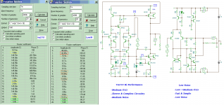
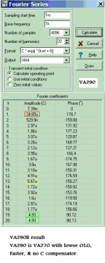
I found something in my sim result. And may be this is why my VA270 still clean compared to VA290, and my VA291 not even reach as good as old VA270 in some case. But where this noise of IMD coming from?
ADD:
I see also 12kHz and 13kHz noise, but 1kHz noise has bigger differences in both VA270&VA290 may be it is the matter.
Attachments
Last edited:
What do you mean when you use the word "resolution"? Distortion? Noise? Linearity? "Resolution" gets tossed around casually, but to have a reasonable technical discussion, we have to start by being specific about what we're saying.
Perhaps your friend should troubleshoot that speed sensor board and fix the defect.
I qualified the word "resolution" by using the word "perception". In case that is too difficult to work out a synonymous phrase might be "perceived by the listener". I attempted to use the descriptors "glare" and "grain" and "artifact" in conjunction with the word "distortion" so once again tying it in to what I heard. I didn't use the word linearity and the word noise has a self evident meaning whenI am talking about what I hear.The reason I use the word "distortion" is that from my experience of the recordings in question those artifacts were present in his system but not the other systems I heard them in.
You made an absolute statement that soundstage is a function of channel separation or crossfeed of out of phase signals. From my observation this is only partially true. It is possible the turntable issue may affect those factors given the MC cartridge is a pretty sensitive vibration transducer, but the separation of the interstage supplies in a monoblock amp?
The speed sensor board holds coils which rotate with the platter, nothing active in the board itself, but thanks for the suggestion.
Last edited:
If stuffing something in it is needed to make the sound OK, it needs to be fixed, coils or not. There's a lot of things that can go wrong in there and by band-aiding a solution, your friend is likely not getting the performance of which his unit is capable.
My statement about soundstaging is in the context of boxes of gain and should not be stretched to include transducers. They are an entirely different matter and not part of this topic.
My statement about soundstaging is in the context of boxes of gain and should not be stretched to include transducers. They are an entirely different matter and not part of this topic.
My statement about soundstaging is in the context of boxes of gain and should not be stretched to include transducers. They are an entirely different matter and not part of this topic.[/QUOTE]
Thereby missing that part of my post concerning amplifier stages.
And the board was not faultyother than the fact it probably suffered from inadequate mechanical design.
Thereby missing that part of my post concerning amplifier stages.
And the board was not faultyother than the fact it probably suffered from inadequate mechanical design.
- Status
- This old topic is closed. If you want to reopen this topic, contact a moderator using the "Report Post" button.
- Home
- Amplifiers
- Solid State
- Feedback affects Soundstage, Imaging, Transients ?