Well guys,you've painted a pretty bleak picture of this amplifier
Sounds like I have a “time bomb” on my hands.I guess I won’t be plugging it back in and I won’t be selling it on then.
So it's that bad that some of you feel that i need to "bin it" What about using it for parts (anything worth selling) or a DIY project to practice on?
Anyway, I haven’t got a lotta money
 and I’ve just wasted £25 on a UXB ,so I’m not a happy chap .I think I’ll stick to the known vintage brands in the future.
I liked the Sansui 101 (did I mention that before) and I think Mooly mentioned that I can reduce the volume/gain by fitting attenuation, because I find every amplifier I’ve tried is too powerful with my speakers .
Thanks to you all for contributing to my thread.
all the best
Dean
Sounds like I have a “time bomb” on my hands.I guess I won’t be plugging it back in and I won’t be selling it on then.
So it's that bad that some of you feel that i need to "bin it"
What about using it for parts (anything worth selling) or a DIY project to practice on? Yep, It’s cut off flush with the PVC outer sheath and the strange thing is (to me that is?) the earth wire is connected at the plug end but not at the amplifier? what’s that about?“The cable is 3-core but the earth wire (I'm fairly certain) is snipped off flush with the PVC outer sheath”
Anyway, I haven’t got a lotta money
I liked the Sansui 101 (did I mention that before
) and I think Mooly mentioned that I can reduce the volume/gain by fitting attenuation, because I find every amplifier I’ve tried is too powerful with my speakers . I've tried this Ian and the "buzz" is still there ( I use a dedicated mains supply to my Hi-Fi ),It also buzzes at my friends house.Did I mention the buzz doesn't increase with volume.With all input leads removed and the system cut back to just the amplifier and speakers, many other possibilities are removed. An electrolytic capacitor (the big ones) then becomes one of the remaining and more likely faults as suggested. Why not try some more simple things first, as it costs nothing
Thanks to you all for contributing to my thread.
all the best
Dean
Thank you Ian this has been a very interesting read
Dean
Hi Dean - 'thought we had lost you after that last flurry of posts. Take heart, the thing has worked and the buzz can be treated but it needs to be looked at by someone with the experience to trace it and a few spare parts like a big electrolytic capacitor or 2 to suit your amp. A few smaller film capacitors shunting the rectifier diodes might help too.
A steady buzz means a steady, noisy source and that will most likely be the rectifier diodes radiating their switching noise out to the nearby circuitry,even idling. In this situation, I would normally suggest replacing the main electrolytic caps and moving the leads about, getting rid of and tidying up that solid wiring to render it less noise-prone. Apart from ignoring electrical safety standards, that is probably the worst electrical fault, I think. Obviously, with there being no earthed chassis, safety is dodgy and care with disconnecting every time you try adjustments is essential. Of course, this makes checking things on the fly impossible.
The black/yellow AC wiring to the rectifier is dragged across the PCB there. That should be twisted together and tucked away, with the transformer rotated to position its leads in the corner, if possible. Basically, all the transformer and power supply wiring should be miles from the amplifier input area but you can logically sort the source of noise, if say, its stronger in one channel and the AC wiring is closer to one input than the other.
On safety, mains leads are cheaply available in quantity and if fitted, would go unquestioned if the product was sold to the public in 3-core but would be blatantly illegal to sell with a 2-core lead unless a class II approval label was permanently attached. That means class II appliance testing or manufacturer's type approval which is not only expensive but unlikely, considering the construction methods. I doubt if NVA's current products are still as woeful as this one, though.
The parts worth saving are the transformer and rectifier - perhaps the case, controls and sockets but the PCB components and output transistors, old electrolytics etc. are worthless. You could salvage the output transistors and their driver transistors too, if you envisage building an old style amp with those particular parts.
I think though, its value is as a DIY amplifier if the earth is fitted properly to the chassis and the alleged design features sacrificed for safety. It would still be worth the 25 quid you paid for it, sealed up and sold untouched for parts, but working as you bought it with appropriate warnings about the design, philosophy and attitude of the manufacturer. Make sure any paperwork cannot be interpreted to mean working "amplifier" or mains appliance.
Thank you so much Ian for your response and advise , I felt all alone at sea , not knowing what direction to paddle . I can’t believe how fast this forum moves there are so many Q&As, one minute you’re here then the next you’re gone! vanished into the abyss
You've given me plenty to think about, I’m not sure I'm up to doing much of the modifications that you've suggested but if I can find someone willing to have a look and give me an estimate I may go down that route in the future when funds permit. I won’t be selling in on it just wouldn’t be right in knowing what I know now.I genuinely believe the chap that sold it to me didn't know because he told me it had been back to the manufacture within the last 18mths and he would have checked it over.
Anyway,I'm going to pick-up a cheap vintage amplifier for the time being so I can have some music.
I'll be attempting to do the re-cap on the Sansui Au-101 (that I swapped with my friend), I’m quite excited, this is the first time I've replaced capacitors on this scale (done the odd one or two on a TV that someone was throwing away because they thought it was broke but it was just a capacitor).
I want to do the job to the best of my ability and as correctly as possible, so I’m going to need a lot of guidance,hopefully the guys on this forum will help me. I’ve been practising with my soldering iron, but I’m going to need to take baby steps. The only think I can offer in return is to document every step (plenty of pics) and place it on here for other learners (like myself) to follow.And of course what I've learned can be past on
Mooly suggested I put a link in from this thread ( do you know how do do that).
Thank you once gain for coming to my rescue Ian
All the best
Dean
, I felt all alone at sea , not knowing what direction to paddle . I can’t believe how fast this forum moves there are so many Q&As, one minute you’re here then the next you’re gone! vanished into the abyssYou've given me plenty to think about, I’m not sure I'm up to doing much of the modifications that you've suggested but if I can find someone willing to have a look and give me an estimate I may go down that route in the future when funds permit. I won’t be selling in on
it just wouldn’t be right in knowing what I know now.I genuinely believe the chap that sold it to me didn't know because he told me it had been back to the manufacture within the last 18mths and he would have checked it over.Anyway,I'm going to pick-up a cheap vintage amplifier for the time being so I can have some music.
I'll be attempting to do the re-cap on the Sansui Au-101 (that I swapped with my friend
), I’m quite excited, this is the first time I've replaced capacitors on this scale (done the odd one or two on a TV that someone was throwing away because they thought it was broke but it was just a capacitor). I want to do the job to the best of my ability and as correctly as possible, so I’m going to need a lot of guidance,hopefully the guys on this forum will help me. I’ve been practising with my soldering iron, but I’m going to need to take baby steps. The only think I can offer in return is to document every step (plenty of pics) and place it on here for other learners (like myself) to follow.And of course what I've learned can be past on
Mooly suggested I put a link in from this thread ( do you know how do do that).
Thank you once gain for coming to my rescue Ian
All the best
Dean
Mooly suggested I put a link in from this thread ( do you know how do do that).
Goto any post in any thread that you want to link to. Click the post number at the right to bring that post to the "top". Then copy the link from the top of your browser and paste it into the thread you want to link to the selected post.
This should link to post #4 of one of your earlier threads,
http://www.diyaudio.com/forums/multi-way/254070-steel-plates.html#post3879116
Attachments

Thank you Mooly for the instructions
Hi Ian, thanks for the suggestion, but I've already taken the plunge and bought this!
Here's some inside shots.
I had to make this up for my speaker cable to fit (the holes were tiny!)
I have some questions please.
Would you know which input is suitable to plug my CD-player into?
There are low & high settings for the Turntable, my cartridge is a Grado Gold, do you know which setting to use.
I haven't tried it yet with any sources because I'm not sure what inputs to use.I don't want to damage anything.Anyone know?
I've connected speakers up to it and it's as pretty silent as I turn the volume up ,there's quite a "thump" on turning the amp on ! but I think the Sansui AU-101 did this as well?
One last thing,do you think it's worth replacing the capacitors?
Once again guys thanks for taking an interest..
Cheers
Dean
A suggestion before your next amplifier purchase, Dean - Post your option here before buying. You'll get strong nays and yays,
but a really bad choice, considering your audio interests, will become clear enough. Collectively, DIYs must have tried the lot!
Hi Ian, thanks for the suggestion, but I've already taken the plunge and bought this!
An externally hosted image should be here but it was not working when we last tested it.
An externally hosted image should be here but it was not working when we last tested it.
An externally hosted image should be here but it was not working when we last tested it.
An externally hosted image should be here but it was not working when we last tested it.
Here's some inside shots.
An externally hosted image should be here but it was not working when we last tested it.
An externally hosted image should be here but it was not working when we last tested it.
An externally hosted image should be here but it was not working when we last tested it.
An externally hosted image should be here but it was not working when we last tested it.
I had to make this up for my speaker cable to fit (the holes were tiny!)
An externally hosted image should be here but it was not working when we last tested it.
I have some questions please.
Would you know which input is suitable to plug my CD-player into?
There are low & high settings for the Turntable, my cartridge is a Grado Gold, do you know which setting to use.
I haven't tried it yet with any sources because I'm not sure what inputs to use.I don't want to damage anything.Anyone know?
I've connected speakers up to it and it's as pretty silent as I turn the volume up
,there's quite a "thump" on turning the amp on ! but I think the Sansui AU-101 did this as well?One last thing,do you think it's worth replacing the capacitors?
Once again guys thanks for taking an interest..
Cheers
Dean
You can't do damage if you keep the Volume low to start with.
Put the CD into the Tuner 2 input switched to low gain.
The pickup will probably need to be switched to high gain, low was more likely for the old and much higher output ceramic or crystal cartridges.
Looks in well cared for condition, good to find one with the speaker plugs and the jack socket filler knob.
Re capacitors: I can't see any leaking or bulging end seals in your pics so I'd leave it alone unless it has an obvious fault, or at least worry about it later.
I hate to be the bringer of bad news, but all those large electrolytic capacitors show blisters in the same relative location and thus breakdown of their seals. The huge one facing down appears to have leaked electrolyte too. They were probably due for replacement 20 years ago - well, how old is a LEAK 30+ amp? It's from the early silicon transistor period, late 1960s no? I don't think I am being at all perfectionist or fussy in saying that if you want to seriously use the amplifier, you are on a journey to find and replace those caps at the very least.
Having just watched a Youtube video of some poor sod who has one of these in very bad shape, with broken, jammed and noisy controls, I think you can be happy not to have his woes, but there is much to be done. The transistors and most components are all replaceable with economical equivalents but their physical size and form will be much smaller which makes them difficult to mount according with the original construction method. Such large can and axial electrolytic caps are all but unobtanium now and of course, buying old stock is pointless.
I was given one of these back around 1990 and the caps were shot, even then. One expects in this warmer climate that electronics will take more of a hiding but it is disappointing to see expensive equipment disabled by component quality when much cheaper alternatives of the day kept soldiering on decades longer.
You can't do damage if you keep the Volume low to start with.
Put the CD into the Tuner 2 input switched to low gain.
Re capacitors: I can't see any leaking or bulging end seals in your pics so I'd leave it alone unless it has an obvious fault, or at least worry about it later.
OK Thanks,.I've just tried it out,it's sounding quite nice with my cd-player,can't turn the volume up much though, to much gain.
Guys I'm confused
with the conflicting opinion on the condition of the capacitors.Ian,are these the caps you're taking about that look suspect (see pic) .Guys I really appreciate your opinion,I know it's difficult just by looking at pictures on the forum ,so is there some way I could test the caps (I've got a multimeter).Would I be able to detect the deterioration by ear if they were no good and if I could what would I be listening for?Sounds like replacing the caps is out of my ability because as Ian as stated
What will happen if I do nothing? will they explode? or will the sound quality just deteriorate? .their physical size and form will be much smaller which makes them difficult to mount according with the original construction method
Guys, have I just bought "another" pig-in-a-poke
I'm gutted if I have.An externally hosted image should be here but it was not working when we last tested it.
Cheers
Dean
You would be unlucky if one were to go pop... usual scenario is the E.S.R. (equivalent series resistance) increase and the capacitance can fall. Both mean reduced performance. Its a bit like replacing a good 2200 uf cap with a 1000uf one together with say a 10 ohm resistor in series with it.
Just 'cos they are old though, doesn't mean they have or are failing, but as with anything, unless proved up to spec you have to be realistic and assume they are past there best.
You need an E.S.R. meter and scope to do meaningful tests. If the PSU caps are failing you might notice more hum than normal, if the signal and speaker coupling caps are failing then sound quality will be impaired in some way... lack of extreme bass, uneven response.
Hi Mooly
Thanks for the reply.
Well,I can't sell the leak on due to "suspect" capacitors (not sure I want to anyhow,I like the sound) I can't test them because I haven't got a E.S.R meter/scope ,so would you be kind enough to help me through the process of trying to change them (assuming I can find alternatives ),where do I start ?
Cheers
Dean
Thanks for the reply.
Well,I can't sell the leak on due to "suspect" capacitors
(not sure I want to anyhow,I like the sound) I can't test them because I haven't got a E.S.R meter/scope ,so would you be kind enough to help me through the process of trying to change them (assuming I can find alternatives ),where do I start ?Cheers
Dean
You need to look at the values and the working voltage. Replacements can be a little higher in capacitance if needed and as high as you want voltage wise. You then need to trawl the usual suppliers to see what is available and if any likely parts will physically fit size wise. If they are a little smaller then you might need new securing hardware to mount them correctly.
Have a look at CPC and RS as a first step and see whats available. Can type caps are used much less these days but there are still many types that are available.
Have a look at CPC and RS as a first step and see whats available. Can type caps are used much less these days but there are still many types that are available.
Hi Mooly...need your help!...not really sure what I'm looking for, I've written down some details off the capacitors.
Blue cap next to silver: 500uf-64v
Silver caps: 1000uf-30VDC
Big silver cap: 2,500uf-50VDC-WKG
Tall blue cap: 800uf-64v
Would something like this be on the right track? It's the same diameter has the Blue capacitor (next to the silver ones) not sure about the values though?
MCHPR100V108M22X32 - MULTICOMP - CAP, ALU ELEC, 1000UF, 100V, SNAP | Farnell UK
Ian
Cheers
Dean
Blue cap next to silver: 500uf-64v
Silver caps: 1000uf-30VDC
Big silver cap: 2,500uf-50VDC-WKG
Tall blue cap: 800uf-64v
Would something like this be on the right track? It's the same diameter has the Blue capacitor (next to the silver ones) not sure about the values though?
MCHPR100V108M22X32 - MULTICOMP - CAP, ALU ELEC, 1000UF, 100V, SNAP | Farnell UK
Ian
Hi Ian,is it purely because of their age,does it mean they deteriorate regardless of usage.Such large can and axial electrolytic caps are all but unobtanium now and of course, buying old stock is pointless.
Cheers
Dean
I have a pdf manual for this - send me a PM with your real email address if you want it.
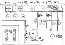
Meanwhile, here is the schematic from Leak Circuits
The big silver cap is marginal on voltage rating (probably why its leaked a bit - I missed that) Make sure replacement is at least 63V
There is also another blue can cap at bottom right under three resistors (C2)
Meanwhile, here is the schematic from Leak Circuits
The big silver cap is marginal on voltage rating (probably why its leaked a bit - I missed that) Make sure replacement is at least 63V
There is also another blue can cap at bottom right under three resistors (C2)
Attachments
I have a pdf manual for this - send me a PM with your real email address if you want it.
Meanwhile, here is the schematic from Leak Circuits
The big silver cap is marginal on voltage rating (probably why its leaked a bit - I missed that) Make sure replacement is at least 63V
There is also another blue can cap at bottom right under three resistors (C2)
Thanks for your offer EssB, but I have one,it came with the amplifier .Unfortunately I don't know how to read a schematic, so it's of no use to me.
You're right there is another cap next to the taller blue one, but I couldn't see any information on it

Do you know if I was on the right track with the link i supplied to that capacitor .
Thank you for your contribution.
Cheers
Dean
The values are all "old" standards.
Blue cap next to silver: 500uf-64v, use 470uf 63 volt.
Silver caps: 1000uf-30VDC, use 1000uf 35 or 63volt.
Big silver cap: 2,500uf-50VDC-WKG, use 2200 or (preferable), 3300uf or 4700uf 63 volt.
Tall blue cap: 800uf-64v, use 1000uf 63 volt.
Blue cap next to silver: 500uf-64v, use 470uf 63 volt.
Silver caps: 1000uf-30VDC, use 1000uf 35 or 63volt.
Big silver cap: 2,500uf-50VDC-WKG, use 2200 or (preferable), 3300uf or 4700uf 63 volt.
Tall blue cap: 800uf-64v, use 1000uf 63 volt.
- Status
- This old topic is closed. If you want to reopen this topic, contact a moderator using the "Report Post" button.
- Home
- Amplifiers
- Solid State
- Faulty Sansui AU101 speaker switch