Thanks for the link! I bought two more straightaway.
New news:
28vdc~30vdc and 8 ohm speaker, gets this amp to image acceptably. After that, it did the imaging/realism performance aspect better than mass market, and the tonality still can't be beat.
I tried 4 ohm load with up to 18vdc, and that was alright; but, I was distracted by the fairly big dynamics and need to analyze it more carefully before commenting further on 4 ohm loads with TDA8932. If 4 ohm load and 15v, it did still sound somewhat like a Toyota car radio. However, the efficiency does result in 5~7 watts more than a normal car chip.
At that point, we'll probably need the datasheet.
The datasheet says 50~55W with an 8 ohm load or 27~30W with a 4 ohm load. For fun, I added 6600uF capacitance series to my 8 ohm load to see what would happen. That was 75W, effectively, with a large-cabinet 8" 8 ohm speaker. The single speaker had as much impact as the paralleled 8 ohm woofer example (the 4 ohm load), at at much less expense for the cabinet size that twice the number of woofers would need. That wasn't new news; however, the new part is that this thing is at least a quarter more efficient than its peers that I compared. Rather than excessively heating the board, this efficiency resulted in much bigger output power which was easily observable, possibly blatant. Ideally, it scales to 1 amplifier board per each woofer.
Old news:
They're really fun, extremely efficient, survive solar applications (Boominator!) easily and they have a friendly tone.
These are not optimal for general purpose use, especially not the TV/movie job; however, the datasheet actually did advise input mods for this problem; so, that is the next thing to explore. . .
For sure, if you can't hit the just-right gain factor then you have to hit the just right voltage. I have observed that this matter is present. After getting the voltage right, then the imaging worked, but the caveats (and benefits) of high gain do still apply.
I'm actually going to explore more power circuit mod attempts before exploring input mods, because we wouldn't want to overdo it on input mods. Anyway, input mods are a last step, because they will end a project. Meanwhile power circuit mods could increase both the stability (unnecessary in this case) and the imaging/realism (quite necessary), so, let's see what happens.
I do still claim that this is the Class D amp for people who don't like Class D sound--it doesn't have any tone inflection other than placidity.
Edit: Did I mention the voltage enough? It does make a difference.
Last edited:
If 4 ohm load and 15v, it did still sound somewhat like a Toyota car radio.
Now that's what i call a premium super objective description.. not.

Can you please go more into detail?
New news:
28vdc~30vdc and 8 ohm speaker, gets this amp to image acceptably. After that, it did the imaging/realism performance aspect better than mass market, and the tonality still can't be beat.
Edit: Did I mention the voltage enough? It does make a difference.
And thanks Daniel for bringing this gem to our attention. This amp hits it out the SQ ballpark given its dimunitive size and even smaller price.
Only issue I have is a faint buzz which I can't get rid of when both modules share a LPS. I've tried a diode in series with each Vp+ line to isolate the boards, varying the supply voltage, using a LT1084 reg, different torroids and power boards, and using an AC power filter. Strangely, only replacing my LPS with a Meanwell smps eliminated the buzz entirely. Unfortunately this smps' 15vdc is well below the voltage I want to operate the amp at. Any suggestion what I should try next with my LPS?
BTW the specs allow for a max 36vdc. Any reason to stop at 30vdc?
Yes, the majority of amplifiers get slightly more stable at lower voltage or slightly less stable at higher voltage.Can you please go more into detail?
Unfortunately, I didn't find out how to adjust the closed loop gain; therefore, the means to adjust for suitable (neither over nor under) compensation, is still rather indirect.
Yes, the datasheet mentions adding a heatsink even at 30vdc. I checked at 32vdc. The chip ran too warm and it flipped the mute rapidly (sounds like popcorn cooking). So, that's a good reason to avoid increasing the voltage further.BTW the specs allow for a max 36vdc. Any reason to stop at 30vdc?
See the datasheet graphs.
Looks like higher audio quality occurs at 28vdc~30vdc, with an 8 ohm speaker.
Possibly, higher voltage could be used if you have a 16 ohm speaker; but, I haven't checked that.
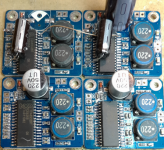
I've gotten some of the Taobao PCBs, they need several mods to get the best from them. Pic attached to demonstrate, some of the mods are hard to spot so I'll spell them out in a little more detail.
1) The input on the PCB is only single ended, but as the IC has a balanced input its best to make use of this functionality. I lifted the cap shunting the -ve input to 0V and installed my own cap, in series with an input attenuator as I don't need quite as much gain as the chip provides natively (36dB in bridged). Also added a shunt cap to turn the attenuator into a LPF - these are being used in an active speaker (Swan D1010) - there's a separate tweeter amp.
2) Get rid of that next-to-useless 220uF/50V SMT cap. I measured its ESR and it was shockingly poor. The NCC KXE (2200uF/25V) I've replaced it with is about 20dB lower resistance and 20dB lower reactance.
3) Decouple the virtual GND (pin12) with a bigger cap (470uF/10V) for improved bass.
4) Since I'm using a pair of these, I've made one master and the other slave in terms of clocking. Pin 31s are joined together between the two amps, the slave amp needs its clock freq determinining resistor (to pin10) reduced to 0R.
Attachments
do you hear a difference after those mods?
i ordered two more of those very similar boards:
35w tda8932 digitalverstrker bordmodul mono low power stereo verstrker in Note about shipping method Dear friends ,Our Free shipping is“Seller's Shipping Method”,Tracking number will be aus Andere elektronische Komponenten auf AliE
i am really surprised how good it sounds without any mods for only about 3 EUR...incredible!
one 8932 is hardwired to a Visaton BG 20 inside a br-box.
it is like they are made for each other.
nice effiency and the bass is just beautiful.
2) Get rid of that next-to-useless 220uF/50V SMT cap. I measured its ESR and it was shockingly poor. The NCC KXE (2200uF/25V) I've replaced it with is about 20dB lower resistance and 20dB lower reactance.
"shockingly poor" is not a number, so what did you measured?
20dB better specs - not a surprise when comparing a 220uF/50V against a 2200uF/25V.
Oh, well, NCC's KXE series is actually starting at 160V, so there's no 25V parts avail.
Beside this, those caps are totally different sizes.
So what about some true informations with right specs?
![A701A8BBE77745FEBB19953EECED9B10[1].jpg](/community/data/attachments/479/479575-5726382fc1c1820a4f90b4237ed73f52.jpg)
I'm using this board.
(the attached photo)
Me too and i love it.
do you hear a difference after those mods?
The only mods this time around I did before/after comparisons were adding the balanced input and operating the two amps as master/slave. Definitely the mods stayed - there were 'offstage noises' which were distracting originally but which got fixed by these two changes. If you're operating only a single amp then maybe a balanced input isn't necessary, but in my stereo implementation its a must. Ditto the syncing of the clocks.
nice effiency and the bass is just beautiful.
Absolutely!
"shockingly poor" is not a number, so what did you measured?
No disagreement there, its definitely not a number. I wrote it because I couldn't recall the precise measurement but I did recall being shocked. So I've just been back to the LCR meter and pulled a cap out of my recycled caps box. Here are the measurements of those SMT caps :
220uF/50V : ESR @ 20kHz 0.26ohm
2200uF/25V : ESR @ 20kHz 0.009ohm
Oh, well, NCC's KXE series is actually starting at 160V, so there's no 25V parts avail.
My poor memory again, thanks for pointing out the error. The parts are KZE, not KXE.
Beside this, those caps are totally different sizes.
You have to be kidding me, no?
I'm using this board.
(the attached photo)
Daniel does that board have alternative options for those SMT caps? Mine has footprints for both through-hole and SMT. If there are two options, definitely replace the SMT caps with some through hole low impedance types.
Yes, the majority of amplifiers get slightly more stable at lower voltage or slightly less stable at higher voltage.
Unfortunately, I didn't find out how to adjust the closed loop gain; therefore, the means to adjust for suitable (neither over nor under) compensation, is still rather indirect.
Yes, the datasheet mentions adding a heatsink even at 30vdc. I checked at 32vdc. The chip ran too warm and it flipped the mute rapidly (sounds like popcorn cooking). So, that's a good reason to avoid increasing the voltage further.
See the datasheet graphs.
Looks like higher audio quality occurs at 28vdc~30vdc, with an 8 ohm speaker.
Possibly, higher voltage could be used if you have a 16 ohm speaker; but, I haven't checked that.
Feedback - my unregulated LPS gives 34vdc. I've played the amp with that for hours without a hiccup, the cards dangling in free air from the back terminals of 8 ohm speakers in the tropics (ambient 30 deg C)
No disagreement there, its definitely not a number. I wrote it because I couldn't recall the precise measurement but I did recall being shocked. So I've just been back to the LCR meter and pulled a cap out of my recycled caps box. Here are the measurements of those SMT caps :
220uF/50V : ESR @ 20kHz 0.26ohm
2200uF/25V : ESR @ 20kHz 0.009ohm
My poor memory again, thanks for pointing out the error. The parts are KZE, not KXE.
You have to be kidding me, no?
No i don't kidding. It is no suprise that a way bigger cap with more uF measures way better than a smaller low uF one. Those SMD/SMT caps are always (more than) a decade behind their through-hole/wired cousins.
May i ask for the resolution/accuracy of your LCR meter?
The KZE datasheet states 0.015R at 100kHz. As ESR is normally higher to lower frequencies i wonder about 0.009R at 20kHz.
Well it was a surprise to me that for its physical size the 220uF/50V had such a poor ESR. I have much smaller case size 220uF/16V caps (non-SMT) and they're about 0.15ohm ESR. Bigger cases normally correlate with lower ESR.
I don't know the accuracy of my LCR meter as its never had a cal, but I've no reason to doubt the measurement. I did do a zero check (probes shorted sets zero) before making the measurement. The measurement is easy to explain - the DS gives the worst case and most caps beat the DS by a fairly wide margin in my experience. I agree that ESR goes down with increasing freq, but the portion 20k-100k is pretty flat in my experience, with less than 10% decrease typically. Whereas going from 20k down to 50Hz the ESR might well go up by an order of magnitude.
The resolution of my LCR meter is 100uohm on ESR, it has force-sense probes.
Last edited:
Bluetooth ? Check here http://m.aliexpress.com/item/32527695215.htmlI have two of these on the way, ran across it when researching for a small portable mono speaker. Has anybody actually listened to one of these with 12v input? The size and form factor is near perfect for my application (small mono battery powered bluetooth speaker).
Sent from my ONE A2001 using Tapatalk
There's no vias under the caps. On that board, the 5 caps paralleled is already low impedance and low inductance too.Daniel does that board have alternative options for those SMT caps? Mine has footprints for both through-hole and SMT. If there are two options, definitely replace the SMT caps with some through hole low impedance types.
There may be a caveat if one of those caps is significantly different from its peers (the Achilles heel of array decoupling); but otherwise, it should work perfectly.
However!
To get audiophile quality from this chip, we'd need to either alter the closed loop gain directly (perhaps pin12?), or un-bridge it.
If it were un-bridged then the signal would go through only one dose of too-high gain rather than two of them. Each 3db is a doubling, the datasheet says 6db difference, so that's 4x less noise, *approximately* and definitely favors un-bridging it for quality reasons. Output caps are involved, but with a rather easy quality control method and custom sizing to fit your particular speaker, performance of medium and smaller speaker can be maximized (the reduction of output power won't be uncomfortable), as can efficiency as well (theoretically). I will try this directly, and report back soon.
The caps that I have seen are rated 35v for just 5000 hours. Likewise, 34vdc is too much, except just for a temporary test situation. This is your opportunity to install a regulator, and turn down the voltage (and noise) a little.Feedback - my unregulated LPS gives 34vdc. I've played the amp with that for hours without a hiccup, the cards dangling in free air from the back terminals of 8 ohm speakers in the tropics (ambient 30 deg C)
Good to know about the durability test. That is astonishing! Thanks for checking. However, I would not expect that condition to be sustainable, long term. So, the follow-up task is some safety derating for the purpose of greater longevity.
- Home
- Amplifiers
- Class D
- Fasten seat belts. TDA8932 pessimistic review.