You have a stereo signal that arrives. To each of the two signal wires (left and right channel) you connect a 10K resistor and the two resistors you connect together in the other end. The signal at this other end is a mono-signal that is formed by resistive summing. This mono signal you connect to the amplifier input "+" terminal and the usual ground to the input "-" terminal. Then it sounds much better.
Last edited:
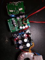
Matt's amps are doing well ") these two are a stacked pair of fully isolated mono amps with independent 14V psu each and 10K:10K transformer input - centre tap to pin 12.
these two are a stacked pair of fully isolated mono amps with independent 14V psu each and 10K:10K transformer input - centre tap to pin 12.
The input transformers are a mere 35H so they sound a little bright - 12kR + 0.022uF across the secondary has mitigated that. They live in homemade shields since they didn't come with any.
14V psu is 50va 2x 15-0 trans, with each regulator having 6600uF smoothing, LT1083 with 12v zener + 1N4007 diode at the base. Although the PCB has two regulators on it, they are not connected at all and work independently.
Amp pin 12 has 220uF Panasonic FC. The other caps are Sanyo 470uF solid polymer. The output filter is designed for 6ohm with Sendust toroids. Sound quality is hard to fault
Some loose ends - the fault light comes on briefly at startup and shutdown since I started using the input trans, and the background is also a tiny bit noisier with trans than with caps - I've yet to do grounding/earth so everything is floating.
So, she's ready for case so then I can do the earth/grounding. Not sure when that will happen tho - work kicks off next week so Christmas hols seems likely.
these two are a stacked pair of fully isolated mono amps with independent 14V psu each and 10K:10K transformer input - centre tap to pin 12. The input transformers are a mere 35H so they sound a little bright - 12kR + 0.022uF across the secondary has mitigated that. They live in homemade shields since they didn't come with any.
14V psu is 50va 2x 15-0 trans, with each regulator having 6600uF smoothing, LT1083 with 12v zener + 1N4007 diode at the base. Although the PCB has two regulators on it, they are not connected at all and work independently.
Amp pin 12 has 220uF Panasonic FC. The other caps are Sanyo 470uF solid polymer. The output filter is designed for 6ohm with Sendust toroids. Sound quality is hard to fault
Some loose ends - the fault light comes on briefly at startup and shutdown since I started using the input trans, and the background is also a tiny bit noisier with trans than with caps - I've yet to do grounding/earth so everything is floating.
So, she's ready for case so then I can do the earth/grounding.
Not sure when that will happen tho - work kicks off next week so Christmas hols seems likely.Attachments
Last edited:
Matt's modules are really getting the best out of the TDA8932 and you have made a very nice amplifier with them. Well done both, and abraxalito who is one of the most knowledgeable on this chip.
But, I will still suggest any "newbie" to buy a couple of $2 blue TDA8932 or TPA3118 modules just to play around with for a start. You will learn a lot and it may happen the modules are ruined before you get tired of them. Then it is time to move on. $4 spend - less than a cinema seat in many countries.
But, I will still suggest any "newbie" to buy a couple of $2 blue TDA8932 or TPA3118 modules just to play around with for a start. You will learn a lot and it may happen the modules are ruined before you get tired of them. Then it is time to move on. $4 spend - less than a cinema seat in many countries.
Does anyone know if it's possible to put volume pots after the transformers? Seems sensible to me to do it after, since doing it before would mean it is affected by the impedance of the transformer and not operate linearly. But then again, with an SE input and a balanced out, I think it's easier to do it before. Sorry, if this is silly Q - it's early and my head hasn't booted well this morning. ;-)
I fully agree with you FauxFrench- although I would perhaps suggest getting the slightly larger red boards? They are rarer but the larger PCB helps with keeping the chip cool and makes it easier to modify if ppl choose to. There's a seller listing them on Ebay but they're "out of stock" right now.

BTW cinema here in HK is $25 for 2D, $30 for 3D, $35 for IMAX. I wish $4
An externally hosted image should be here but it was not working when we last tested it.
I fully agree with you FauxFrench- although I would perhaps suggest getting the slightly larger red boards? They are rarer but the larger PCB helps with keeping the chip cool and makes it easier to modify if ppl choose to. There's a seller listing them on Ebay but they're "out of stock" right now.
BTW cinema here in HK is $25 for 2D, $30 for 3D, $35 for IMAX. I wish $4
Last edited:
Thanks! Matt's design already has 4k7 series resistors on the inputs (R10 and R13) so I can remove the shunt resistor (r11 is 22k) and put the pot there as the easiest option, or if I got this right, replace r11 with 47K and wire the 50K pot in parallel with R11.
Last edited:
sanwu board
Sory but the schematics is still missing something. On the sanwu board pins 14 and 15 are not connected.
Sorry, missed the negative grounding, matt_garman.
Just confirmed that the negative input is grounded on my board. The corrected schematic is attached...
Sory but the schematics is still missing something. On the sanwu board pins 14 and 15 are not connected.
Hi,
Hberner schematic is correct. On the blue Sanwu boards pin 2 is connected to pin 14 and pin 3 is connected to pin 15 - the same as the schematic. I have these blue Sanwu boards and just checked with my DMM - they are connected correctly, the same as the schematic. If that is not the case with the boards you have, something is faulty.
Hberner schematic is correct. On the blue Sanwu boards pin 2 is connected to pin 14 and pin 3 is connected to pin 15 - the same as the schematic. I have these blue Sanwu boards and just checked with my DMM - they are connected correctly, the same as the schematic. If that is not the case with the boards you have, something is faulty.
I just did (another) listening test between the TPA3118 and TA2020. See here -I'm still a fan of the TA2020 and the best is a Charlize II of the ones I've tried - I still listen to this amp all the time. I prefer the warmth of this to the clinical 3118/6.
http://www.diyaudio.com/forums/class-d/322666-ta2020-vs-tpa3118-vs-tda8932-comparison.html#post5539856
I now agree with you!
Figured it would be easy to connect this thing but im having really poor results. did i connect it badly?
here is the one i purchased:
TDA8932 35W Digital Amplifier Board Module Mono Power
Made a fast schematic, here is how i connected it:
https://i.imgur.com/WJavyky.jpg
The 4 1000uF capacitors are there to stabilize the powersupply being of switching type.
The sounds is pretty terrible, i can defenitly turn it up loud enough but the high's are missing. it sounds very boomy. there is also a hum even when not playing anything. Im using my headphone amp as input. i hear absolutely no hum whatsoever when using the headphone amp with headphones, not even when i turn it far up.
i tried playing from phone instead and its got a different hum but its still there. but the big issue is really the lacking sound quality.
Any ideas? i should probably also point out that im using new speakers so im not sure how they are supposed to sound, but i cant imagine my new 10 times more expensive speakers are supposed to sound 10 times worse.
Here is a tragic EQ i used on my phone to make it sound much better. There is a huge falloff on higher frequncies so made up for it with EQ. gives a pretty good idea on how the speakers sound right now.
Phone EQ
Last edited:
Yes there is no connection between audio ground and power supply ground, was kind of expecting the ground to be shared directly on the TDA chip but maybe it isnt?
should i just make a direct connection between power supply ground and audio ground? i belive they should have same potential (0v).
should i just make a direct connection between power supply ground and audio ground? i belive they should have same potential (0v).
So long as your inputs are AC coupled (capacitors in between the source and the pins of the TDA8932) then yes you do need an explicit connection. The inputs of TDA8932 are differential so the -ve one isn't grounded except with some PCBs there's just a single ended input and the -ve one is AC grounded. Even then you do need a DC connection between input GND and PSU GND.
i think i understand what i think you said but i'm not sure i realize that what you said is not what you meant.
sorry, english is not my native language and im not used to some of these wordings, im not following on the AC coupling part. My connection is AC coupled because i have capacitors where? source is the audio source or voltage source? and what pins on the TDA8932, the input pins?
i just did some probing with multimeter though, and i have 0 ohm between power supply ground and audio input ground. Guess its a shared ground after all, or do i need something more?
Given you have 0 ohm between audio input GND and PSU GND then the absence of such a connection isn't your problem.
When I wrote 'source' I meant signal/audio source, not DC source. And yes, the input pins of TDA8932.
Looking closer at the PCB you linked I see the -ve input is already at GND. So the module's input is single-ended.
When I wrote 'source' I meant signal/audio source, not DC source. And yes, the input pins of TDA8932.
Looking closer at the PCB you linked I see the -ve input is already at GND. So the module's input is single-ended.
Last edited:
Alright thanks for clarifications! But not sure what might be the problem then... its almost like theres a low pass filter on the audio signal. i think i will bring it to my university and borrow their singal generator and oscilloscope. maybe i will see something happen with the output depending on frequency?
- Home
- Amplifiers
- Class D
- Fasten seat belts. TDA8932 pessimistic review.