The Sonar U7 has got high performance circuits inside, including a headphone amplifier. That requires quite some current. Could it be that the Sonar U7 is simply starved from current and performs marginally (the buzz'ing) because of that?
Not likely. If there is no low impedance load, its drawn current is very low.
Thanks for thinking with me. I use a 2A power supply for my RPI. I have measured the power consumption of the RPI together with the Xonar and its stable at 5W. Besides the Xonar is performing very well with different kinds of amplifiers. I think I have solved the buzz problem of the 8932's, I think it was caused by the LED screen that was connected to the RPI. Without this screen its silent.I have a Raspberry PI3 and that one is supplied from a rather moderate 5V supply (as recommended). That must mean, that little current is available for the USB outputs.
You supply your Sonar U7 from the RPI USB connector, thus, from the same power supply as for the micro-computer, am I wrong?
The Sonar U7 has got high performance circuits inside, including a headphone amplifier. That requires quite some current. Could it be that the Sonar U7 is simply starved from current and performs marginally (the buzz'ing) because of that?
Two ways to check: with a laptop or with a USB hub having its own 5V supply. If so, the USB hub with own supply may be a solution because the RPI supply is relieved from the Sonar U7 as load.
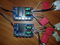
In the meantime I have modded the 8932's. I made my own chockes by wiring waxed copperwire on coils that I removed from another device. I needed only 8 windings to get a value of about 22uH. I replaced the smd capacitor by a 0,47 uF foil type. They are playing well, but I am not sure if the music quality is improved. I am thinking of modding the input filter too, but which capacitors shoudl be replaced and what values should I use?
Attachments
I needed only 8 windings to get a value of about 22uH.
The original choke got 220µH, not 22.
I have a question regarding decoupling caps: I want to replace them because the amp sounds harsh at high volumes. I'm using 2x18650 with xl6009 step up module at 28-30v. Now the question: Is it better to change from 5x100uf stock caps to 3x low esr 1000uf 35v panasonics (with jumpers in between each skipped trace) or buy 3x Samwha 1000uf 50v ones so the voltage margin is higher?
The original choke got 220µH, not 22.
The original choke is 22uH. "220" -> a two and a two and no zeroes. At least all mine are so. Also, this is what NXP recommends.
See table 14 on page 24 of the datasheet.
Last edited:
Thanks for thinking with me. I use a 2A power supply for my RPI. I have measured the power consumption of the RPI together with the Xonar and its stable at 5W. Besides the Xonar is performing very well with different kinds of amplifiers. I think I have solved the buzz problem of the 8932's, I think it was caused by the LED screen that was connected to the RPI. Without this screen its silent.
In the meantime I have modded the 8932's. I made my own chockes by wiring waxed copperwire on coils that I removed from another device. I needed only 8 windings to get a value of about 22uH. I replaced the smd capacitor by a 0,47 uF foil type. They are playing well, but I am not sure if the music quality is improved. I am thinking of modding the input filter too, but which capacitors shoudl be replaced and what values should I use?
I am very happy to hear you found a solution. This is what characterizes good engineers - they never give up before a solution is found. And, the TDA8932 has a really nice sound.
The initial input "filter" is not really a filter in the sense that all you can change are the two input coupling capacitors.
The initial input coupling capacitor values should be 1uF. They are small ceramic SMD type capacitors. They suffer from non-linearity and piezo- electric properties. Therefore, you should use foil capacitors of the same value instead.
If you look at Fig.37 of the datasheet, they are the two 1uF capacitors connected to pins 2 and 3. Be aware that the TDA8932 board you have is not with a differential input such that the capacitor connected to pin 3 is grounded on the other terminal. Only the capacitor connected to pin 2 is used as input (marked with "+").
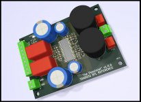
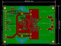
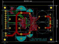
Creating a PCB for this chip has been on my todo list for a while, so I whipped up something pretty quickly. In honor of this thread, I call it "The Pessimist". The goal here is to be a basic BTL reference implementation (for single-rail PSU). The schematic is almost copied exactly from page 38 of the datasheet, with some obvious "inspiration" (ok, outright copying) from curtvm's design (post #455/page 46). I added space for more/bigger PSU decoupling caps.
If this works and seems decent, then I envision a version 2 with more features, tweaks, etc.
The schematic is in the attached PDF file.
Happy to hear any thoughts on the design and/or layout!
If this works and seems decent, then I envision a version 2 with more features, tweaks, etc.
The schematic is in the attached PDF file.
Happy to hear any thoughts on the design and/or layout!
Attachments
I have a question regarding decoupling caps: I want to replace them because the amp sounds harsh at high volumes. I'm using 2x18650 with xl6009 step up module at 28-30v. Now the question: Is it better to change from 5x100uf stock caps to 3x low esr 1000uf 35v panasonics (with jumpers in between each skipped trace) or buy 3x Samwha 1000uf 50v ones so the voltage margin is higher?
I assume you are talking about TDA8932 as well.
XL6009 is capable of supplying what corresponds to 4A at the input! You do not write what is your input voltage but let's assume 12V. Then you have 12/30*4 = 1.6 Amp at the output, minus converter losses. Let's assume some 1.4 Amp. 1.4 Amp is not taking you far, in particular if you use less than 8 Ohm speakers. Better buffer capacitors will not save you if the converter simply enters current limitation.
The five 100uF stock caps you better let stay because they may be needed for stability. Add caps only.
A boost converter has got a nasty output ripple (the Buck converter a nasty input ripple). You should have several thousand uF at the output and it should be low ESR because your boost converter is supplying current bursts (from zero) and your TDA8932 is consuming with a 300-400KHz modulation frequency intermingled. The buffer capacitors are really under "fire".
First, you need to find out if the power converter really current-limits when you play loud. One thing you could do is to adjust the output voltage to 18V and see if the problem is the same. At 18V you have more current at your disposal.
Secondly, use your 3x1000uF low ESR on each output and see if that helps. If you are not in current limitation of the boost converter, it should help. Check with a voltmeter that the output voltage is stable and not oscillating.
Step up converters are in principle a simple solution to the need for a higher amplifier supply voltage. In practice it requires very good filtering at the output.
Last edited:
Creating a PCB for this chip has been on my todo list for a while, so I whipped up something pretty quickly. In honor of this thread, I call it "The Pessimist". The goal here is to be a basic BTL reference implementation (for single-rail PSU). The schematic is almost copied exactly from page 38 of the datasheet, with some obvious "inspiration" (ok, outright copying) from curtvm's design (post #455/page 46). I added space for more/bigger PSU decoupling caps.
If this works and seems decent, then I envision a version 2 with more features, tweaks, etc.
The schematic is in the attached PDF file.
Happy to hear any thoughts on the design and/or layout!
Seems very good: Foil capacitors on the input and output.
Comments:
You use 2.2uF as input coupling capacitors, NXP recommends 1uF.
You use a 10uH/1.5uF output filter. That is optimized for 4 Ohm. Could it be more universal with a 15uH/1uF filter optimized for 6 Ohm?
You use filter chokes with a physical outline I do not know.
Are the output filter capacitors really so much smaller than the input coupling capacitors?
I am one of those who cannot get enough power line decoupling. You have space to increase your 220uF decoupling capacitors to 1000uF. If you want to use the TDA8932 potential to its full, 6400uF is not too much I would say.
Good initiative!
The original choke is 22uH. "220" -> a two and a two and no zeroes. At least all mine are so. Also, this is what NXP recommends.
See table 14 on page 24 of the datasheet.
You are right, I apologize.
I have a question regarding decoupling caps: I want to replace them because the amp sounds harsh at high volumes.
To kill the harshness the supply that needs decoupling is the analog signal rail (pin 8). If you add extra decoupling there you'll not need more on the main supply.
Happy to hear any thoughts on the design and/or layout!
Hi Matt
A few suggestions with this, based on my experience of tweaking quite a number of 8932 implementations to optimize the SQ :
1) You won't need the 4 electrolytics ( C1, C21-23) on the main supply. Suggest just one 2200uF and put the two smaller ones where it really matters, on pin8. Or just go with one 470uF/35V on pin8. I'm assuming this is one of your 80/20 designs and you don't want to go to the trouble of a separate regulator for the pin8 supply

2) Add series resistors to the input pins (2,3, 14, 15) of 470R. This helps keep down RFI from being coupled to the inputs from the output wiring.
3) Increase the cap on pin12 to 470uF/6.3V. Improves the already extremely good bass.
4) Add 1M resistors across C6,C15. This allows using the non-B variant of the chip.
I haven't taken a look at the layout, I'd rather spend that time on my own design which has been languishing at the post-placement stage for about a month
Thank you. That's new to me because I was referring to this TPA3118 modding thread while it seems similar to TDA8932 amplifier:To kill the harshness the supply that needs decoupling is the analog signal rail (pin 8). If you add extra decoupling there you'll not need more on the main supply.
Improving TPA3118 Class D Amplifier | HiFiVision.com
The person there says he changed four 330uF decoupling caps to better 470uf caps and that made the most improvement regarding
As far as pin 8 caps go, what type, voltage and value caps do I need? Should they go from pin 8 to the next component in the trace? Thanks.
P.S. I've made a portable speaker and will be posting more details, once I finish with amplifiers and get my 4x18650 holders.
TPA3118 has a similar structure in that there's an analog supply rail for the signal level circuits (pin17, AVCC) but there's zero additional decoupling for that pin on most boards. TI's application circuits don't suggest it needs anything extra. NXP on the other hand do add a 10R series resistor and a cap specifically for that pin (pin8).
I did mod my first TPA3116 with extra decoupling for pin17 and it gave a substantial improvement. Its a tricky mod to do though as you need to lift the pin from the PCB. Given the 10R resistor isolating pin8 from the main supply on the typical TDA8932 board, the addition of decoupling caps to that pin is much easier. They go from pin8 to GND, the value I'd suggest as a minimum is 470uF.
I did mod my first TPA3116 with extra decoupling for pin17 and it gave a substantial improvement. Its a tricky mod to do though as you need to lift the pin from the PCB. Given the 10R resistor isolating pin8 from the main supply on the typical TDA8932 board, the addition of decoupling caps to that pin is much easier. They go from pin8 to GND, the value I'd suggest as a minimum is 470uF.
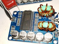
I replaced the input capacitor by 1 uF foil capacitor (see picture). I did some more listening tests and have some observations:I am very happy to hear you found a solution. This is what characterizes good engineers - they never give up before a solution is found. And, the TDA8932 has a really nice sound.
The initial input "filter" is not really a filter in the sense that all you can change are the two input coupling capacitors.
The initial input coupling capacitor values should be 1uF. They are small ceramic SMD type capacitors. They suffer from non-linearity and piezo- electric properties. Therefore, you should use foil capacitors of the same value instead.
If you look at Fig.37 of the datasheet, they are the two 1uF capacitors connected to pins 2 and 3. Be aware that the TDA8932 board you have is not with a differential input such that the capacitor connected to pin 3 is grounded on the other terminal. Only the capacitor connected to pin 2 is used as input (marked with "+").
- The chokes are getting pretty warm. I have a laser thermometer and measured 50 degrees Celcius at the core
- There is a problem with the sound: especially with loud passages there is some distortion in the mid. This is recognizable with voices. The bass and treble seem not to be affected.
I suspect the chokes that I winded myself. Perhaps the core is not suitable for this appliance. I saw some considerations regarding the chokes on diybudgetaudio. This small amplifier needs suprisingly heavy chokes that are difficult to find with prices that are higher than the amplifier itself. Can you recommend?
Attachments
I bought a number of those yellow-blue'ish chokes from out east and tried more of them in class D output filters. In best case they started getting warm, in worst case they affected the sound (negatively) of the amplifier. The cores seem to have high losses and the permeability at higher frequencies may drop. I haven't had time to set up a measuring circuit. My conclusion is these yellow-blue'ish cores are no good for class D output filters.
Mine remain in the drawer.
I have better experience with these 15uH/15A chokes:
5pcs/KS065060 17MM Iron silicon aluminum 15UH 1.2 Line 10A Magnetic ring inductors Annular inductance-in Inductors from Home Improvement on Aliexpress.com | Alibaba Group
And, I recently made a filter with these chokes (also 15uH) which works very well:
2pcs/SMD Integral forming inductors 1770 15UH 12A Saturated 20A 17*17*7MM Printing:150-in Inductors from Home Improvement on Aliexpress.com | Alibaba Group
I have now ordered 22uH SAGAMI inductors I expect to work well:
10pcs new Digital amplifier dedicated shielded inductor 7G17A 22uH -in Replacement Parts from Consumer Electronics on Aliexpress.com | Alibaba Group
Yes, a good filter costs more than the ("dirt cheap") amplifier. The amplifiers are spit out by a robot without a break, the chokes may require human intervention. It is probably the amplifier that is particularly low priced rather than the chokes being particularly expensive, at least from a European perspective.
Last edited:
Thanks for your suggestions. With all these options a core is used that can saturate. Why not use aircoils like they are used for passive crossover filters? At low values they are affordable Luchtspoel 0.70mm - RumoH - Caps, Coils and Speakers You can unwind them till you get the right value.I bought a number of those yellow-blue'ish chokes from out east and tried more of them in class D output filters. In best case they started getting warm, in worst case they affected the sound (negatively) of the amplifier. The cores seem to have high losses and the permeability at higher frequencies may drop. I haven't had time to set up a measuring circuit. My conclusion is these yellow-blue'ish cores are no good for class D output filters.
Mine remain in the drawer.
I have better experience with these 15uH/15A chokes:
5pcs/KS065060 17MM Iron silicon aluminum 15UH 1.2 Line 10A Magnetic ring inductors Annular inductance-in Inductors from Home Improvement on Aliexpress.com | Alibaba Group
And, I recently made a filter with these chokes (also 15uH) which works very well:
2pcs/SMD Integral forming inductors 1770 15UH 12A Saturated 20A 17*17*7MM Printing:150-in Inductors from Home Improvement on Aliexpress.com | Alibaba Group
I have now ordered 22uH SAGAMI inductors I expect to work well:
10pcs new Digital amplifier dedicated shielded inductor 7G17A 22uH -in Replacement Parts from Consumer Electronics on Aliexpress.com | Alibaba Group
Yes, a good filter costs more than the ("dirt cheap") amplifier. The amplifiers are spit out by a robot without a break, the chokes may require human intervention. It is probably the amplifier that is particularly low priced rather than the chokes being particularly expensive, at least from a European perspective.
You use 2.2uF as input coupling capacitors, NXP recommends 1uF.
I mainly did that just to induce a slightly bigger capacitor footprint. I was trying to strike a balance between flexibility (which typically calls for lots of space) and smallish footprint. Also, though the math says otherwise, in one of the tpa311x threads, people claimed bigger input decoupling values improved bass.
You use a 10uH/1.5uF output filter. That is optimized for 4 Ohm. Could it be more universal with a 15uH/1uF filter optimized for 6 Ohm?
Of course, the footprints "should" support any output filter values you want to use. I assumed 4R speakers because that's what I'll be using.
But since this is a bare board, the user can populate the right filter values for his speaker load. When I get ready to have these fabbed, I'll write a BOM with notes on component selection.You use filter chokes with a physical outline I do not know.
Those are 18mm radius, 10mm lead spacing footprints. I had something like the Coilcraft RFS1412 series in mind. Although looking at that DS now, I see those are only 13.5mm diameter, not sure where I came up with 18mm.
At any rate: my thoughts on the inductors were, just give enough space for something decent, i.e. better than the likely-underrated ones that come with the cheap boards from China.
Definitely worth further discussion/investigation. I need to find the tpa311x thread where doctormord did a bunch of inductor testing, and maybe go with that. My goal here is to have something that meets the current (amperage) requirement; is easy to obtain; and not expensive.
Are the output filter capacitors really so much smaller than the input coupling capacitors?
Yes, because I was assuming polypropylene caps for input, which tend to be bigger; and polyester for output, which tend to be smaller.
I am one of those who cannot get enough power line decoupling. You have space to increase your 220uF decoupling capacitors to 1000uF. If you want to use the TDA8932 potential to its full, 6400uF is not too much I would say.
The bigger caps are 16mm diameter. A quick Mouser check says you can get 35v rated electrolytics up to 6600uF (e.g. United Chemi-Con ELBK350ELL662AL40S). And there are lots available in the 3300-4700uF range in this footprint.
1) You won't need the 4 electrolytics ( C1, C21-23) on the main supply. Suggest just one 2200uF and put the two smaller ones where it really matters, on pin8. Or just go with one 470uF/35V on pin8. I'm assuming this is one of your 80/20 designs and you don't want to go to the trouble of a separate regulator for the pin8 supply
This may not even be as ambitious as an 80/20 design.
This is a warm-up exercise, I don't want to stray too far from the datasheet. Basically, I just want to be one step above the cheap ebay/aliexpress stuff. That is, a schematic is provided to avoid guesswork and surprises; use your own components to avoid fakes or under-rated parts; use your own solder for easier modding.A dedicated pin8 regulator is definitely version 2 material, but an extra cap here or there probably doesn't break the design philosophy too much.
2) Add series resistors to the input pins (2,3, 14, 15) of 470R. This helps keep down RFI from being coupled to the inputs from the output wiring.
Easy enough. Version 2 will have pads for gain-setting resistors as well.
3) Increase the cap on pin12 to 470uF/6.3V. Improves the already extremely good bass.
The DS shows a 100nF cap there. Should that remain? When I see tiny ceramics like that, I just assume the main purpose is HF filtering...
4) Add 1M resistors across C6,C15. This allows using the non-B variant of the chip.
When using the B variant of the chip, should those resistors simply be left off?
I haven't taken a look at the layout, I'd rather spend that time on my own design which has been languishing at the post-placement stage for about a month
Thanks for your feedback! I don't think the layout is anything special, as the main intent is to be a simple reference design. Hopefully it doesn't make any glaring errors.
Thanks for your suggestions. With all these options a core is used that can saturate. Why not use aircoils like they are used for passive crossover filters? At low values they are affordable Luchtspoel 0.70mm - RumoH - Caps, Coils and Speakers You can unwind them till you get the right value.
Personally, the idea of a considerable "leakage" field from air-coils does not appeal to me. But, I have seen more apparently serious constructions made with air-coils so I cannot state it won't work well. If you do not try, you won't know.
Let us know if it works well.
At least also I have bad experience with the yellow-blue'ish toroid cores and they should be changed.
When I buy rather unspecified chokes from out east, I know I take a risk on the non-specified parameters of the cores. Some you win - some you loose.
- Home
- Amplifiers
- Class D
- Fasten seat belts. TDA8932 pessimistic review.