anatech said:Hi Alex,
In the old days, they were included in the data book, also at the end under application notes. Of course we are talking about Motorola.
This is an article describing breakdown modes for power transistors from the On Semi site. I am sure there are others hiding around town.
-Chris
Thank you for the link.
By the way, i saw a previus post about MOSPEC transistors, i found some 2SC3281/2SA1302 of that company and the price is cheap enough .
These are probably originals because a company that makes fake transistor would probably print a known brand and not MOSPEC but i wonder how does it compare to original toshiba transistor, will it have the same material quality (case and construction).
On the other hand its better to have a generic from mospeg than a fake.
Alex
Hi
I found the attached schematic in a web site (i don't remenber where) and i was wondering if it actually works (for big transistors).
It could be modified with 10W resistors in series insted of the bulb (maybe for other values with smaller transistors for less current) and a transformer for me (which i have) because of different mains (220v).
I suppose that the testing time should be a couple of seconds.
IF YOU TRY THIS THEN BE CAREFULL BECAUSE THERE ARE DANGEROUS HIGH VOLTAGES INVOLVED
Alex

Attachment deleted. Line operated with no isolation and the device will be handled frequently.
I found the attached schematic in a web site (i don't remenber where) and i was wondering if it actually works (for big transistors).
It could be modified with 10W resistors in series insted of the bulb (maybe for other values with smaller transistors for less current) and a transformer for me (which i have) because of different mains (220v).
I suppose that the testing time should be a couple of seconds.
IF YOU TRY THIS THEN BE CAREFULL BECAUSE THERE ARE DANGEROUS HIGH VOLTAGES INVOLVED
Alex
Attachment deleted. Line operated with no isolation and the device will be handled frequently.
Hi Alex,
This circuit is both unnecessary and dangerous. I had to delete the attachment because of this. You can achieve the same thing in a safer manner, but I still do not recommend it. There are heatsinking considerations as well. What you should do is apply a set voltage and allow the specified current for a set time (pulse). This will allow a better test where a heatsink is less critical.
SOA testing is best left to a lab.
-Chris
anatech said:Hi Alex,
This circuit is both unnecessary and dangerous. I had to delete the attachment because of this. You can achieve the same thing in a safer manner, but I still do not recommend it. There are heatsinking considerations as well. What you should do is apply a set voltage and allow the specified current for a set time (pulse). This will allow a better test where a heatsink is less critical.
SOA testing is best left to a lab.
-Chris
Hi
I posted the schematic as i found it in the internet and i wrote a warning inside the post but maybe you were right to delete it because you never know who might try it at home.
It just seemed a very simple way to test a transistor...
Sorry for that
Alex
Hi Alex,
It's easy for some of us to know how to handle AC circuits, although I'd use an isolation transformer at the very least. Other members starting out simply have no idea what is dangerous. Try to anticipate what a complete rookie may think of.
No problem otherwise.") I also don't think that is the best way to test for SOA either, see my comments in the quote.
I also don't think that is the best way to test for SOA either, see my comments in the quote.
-Chris
It's easy for some of us to know how to handle AC circuits, although I'd use an isolation transformer at the very least. Other members starting out simply have no idea what is dangerous. Try to anticipate what a complete rookie may think of.
No problem otherwise.
I also don't think that is the best way to test for SOA either, see my comments in the quote.-Chris
Hi Nixie,
I don't want to spend any time that we have on this, but a switcher is a little different.
Yes, a switching power supply is partly live, however the nature of the project should keep most untrained people out of it. The other issue is that the posted diagram could have been executed with DC power just as well, or with an isolation transformer. It was also not a reliable way to test for SOA anyway - so no loss there. It was simple enough to be incredibly dangerous and the circuit would be constantly handled in use as someone tested their parts. Not a good combination.
So, no direct mains connected circuitry with some exceptions, like switching power supplies. Attendant warnings and all that.
Nixie said:Please repost the schematics or email them to me; I want to see.
I can email you the picture but you have disabled the option that allows you to receive emails from other members.
I don't know if it's working or not and did't try it either so i can't take responsibility for anything, i just found it in a web site for fake transistors.
Alex
Motorola MJ15024
Hi everyone,
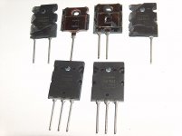
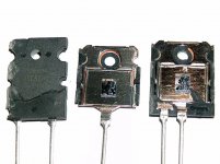
I need your help. I bought some Motorola MJ15024 transistors.
I think they are genuine Motorola. But aslo I am not sure. I took some pics. There are some damage inside. Because, I could open it via drill only.
http://img.photobucket.com/albums/v170/muffy1063/IMG_4532.jpg

Hi everyone,
I need your help. I bought some Motorola MJ15024 transistors.
I think they are genuine Motorola. But aslo I am not sure. I took some pics. There are some damage inside. Because, I could open it via drill only.
http://img.photobucket.com/albums/v170/muffy1063/IMG_4532.jpg
More Counterfeit MJ15024s e-bay
Please look at the listing:
http://cgi.ebay.com/50-NPN-MJ15024-...5|66:2|65:12|39:1|240:1318|301:1|293:1|294:50
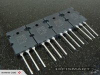
Has anyone ever seen Motorola transistors with a mounting surface as shown? It is rough and uneven. Furthermore as far as I know Motorola does not make T03 output transistors now. I have used MJ15024s for many years. These must be counterfeit. This kind of seller is making e-bay a marketplace for crooks... Anyone who buys these is being cheated and effectively robbed.
Please look at the listing:
http://cgi.ebay.com/50-NPN-MJ15024-...5|66:2|65:12|39:1|240:1318|301:1|293:1|294:50
Has anyone ever seen Motorola transistors with a mounting surface as shown? It is rough and uneven. Furthermore as far as I know Motorola does not make T03 output transistors now. I have used MJ15024s for many years. These must be counterfeit. This kind of seller is making e-bay a marketplace for crooks... Anyone who buys these is being cheated and effectively robbed.
- Status
- This old topic is closed. If you want to reopen this topic, contact a moderator using the "Report Post" button.
- Home
- Design & Build
- Parts
- Fake *******ING "MOTOROLA" Transistors