Member
Joined 2009
Paid Member
The cfp changes the sound a lot; that's been my experience. It's very clean sounding when used as an LTP and I'd recommend it for a bass amp in a multi-amp system because it seems to excel in this area.
For FETs with cfp input I'd be looking here: MJR-7 Mosfet Power Amplifier.
For FETs with cfp input I'd be looking here: MJR-7 Mosfet Power Amplifier.
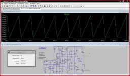
Some further testing with evaluation of PSU ripple rejection.
This was a potential problem area in the M1 and an area that needed to be improved. The new design uses two rails, a higher voltage stabilised supply for the input stages and the normal unregulated feed for the output stages. As the current requirements are low for the input stage a voltage double and regulator could be used to obtain the higher supply.
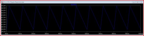
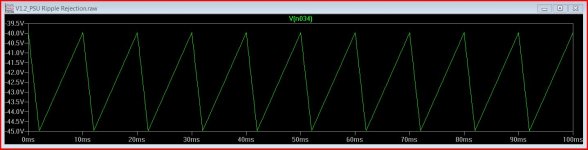
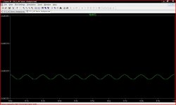
The test here is severe with 5 volts pk/pk of 100hz ripple on each rail. For comparison I have included a plot of the M1 under the same conditions. 126uV versus 12 mv. The two smaller pictures are the rail ripple.
This was a potential problem area in the M1 and an area that needed to be improved. The new design uses two rails, a higher voltage stabilised supply for the input stages and the normal unregulated feed for the output stages. As the current requirements are low for the input stage a voltage double and regulator could be used to obtain the higher supply.
The test here is severe with 5 volts pk/pk of 100hz ripple on each rail. For comparison I have included a plot of the M1 under the same conditions. 126uV versus 12 mv. The two smaller pictures are the rail ripple.
Attachments
 Per request I have moved all of the bipolar amp version related posts to this new thread: http://www.diyaudio.com/forums/soli...p-single-ended-input-stage-inpired-mooly.html
Please stick to the topic and don't post here about the bipolar version.
The Servo
The original M1 used a TL071 for a DC servo and bias generator to provide the required -3.5 volts or so bias needed by the single ended input stage.
This was one area that needed a major rethink because the opamp output has significant audio present the amplitude of which rises as frequency goes down.
In the F_V I have looked at a "fixed" bias scheme with a very mild servo input that does little more than trim and maintain the offset at the zero point. R29 and 31 derive a fixed bias from a zener reference. R29 would be a 22K multiturn trimpot and used to initially adjust the servo output to some suitable value (the output of the amp proper will snap to zero volts when the servo is working within its limits hence "setting the output of the servo to some suitable level"). That level should really be a point that allows equal offsets to be compensated for. Looking at the minute details another thought arose. Is it worth biasing the opamp into Class A by sourcing or sinking a current into the output pin. Although the audio present is miniscule is it a detail worth attending too.
At this point I find myself struggling with LTspice. Notice the 0.99uf input coupling cap. Any value up to and including 0.99uf works in simulation. 1uf and above and the simulation doesn't run (well it does but at around a few ns per second of real time so it would take years). Similarly even a 100K from the opamp output to the -15 volt rail does the same. I have no idea why that should upset the simulation, maybe someone has some insight on that.
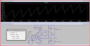
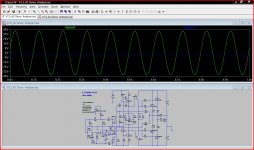
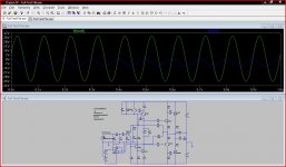
So for comparison here are the plots of the two amplifiers at 10Hz and maximum output. Notice the high output from the servo in the M1 which is just going into clipping at this point. The output from the F_V is minimal as can be seen in the detail shot.
And my thanks to the mods for cleaning this thread up.
The original M1 used a TL071 for a DC servo and bias generator to provide the required -3.5 volts or so bias needed by the single ended input stage.
This was one area that needed a major rethink because the opamp output has significant audio present the amplitude of which rises as frequency goes down.
In the F_V I have looked at a "fixed" bias scheme with a very mild servo input that does little more than trim and maintain the offset at the zero point. R29 and 31 derive a fixed bias from a zener reference. R29 would be a 22K multiturn trimpot and used to initially adjust the servo output to some suitable value (the output of the amp proper will snap to zero volts when the servo is working within its limits hence "setting the output of the servo to some suitable level"). That level should really be a point that allows equal offsets to be compensated for. Looking at the minute details another thought arose. Is it worth biasing the opamp into Class A by sourcing or sinking a current into the output pin. Although the audio present is miniscule is it a detail worth attending too.
At this point I find myself struggling with LTspice. Notice the 0.99uf input coupling cap. Any value up to and including 0.99uf works in simulation. 1uf and above and the simulation doesn't run (well it does but at around a few ns per second of real time so it would take years). Similarly even a 100K from the opamp output to the -15 volt rail does the same. I have no idea why that should upset the simulation, maybe someone has some insight on that.
So for comparison here are the plots of the two amplifiers at 10Hz and maximum output. Notice the high output from the servo in the M1 which is just going into clipping at this point. The output from the F_V is minimal as can be seen in the detail shot.
And my thanks to the mods for cleaning this thread up.
Attachments
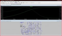
The output of the DC servo at subsonic frequencies, below the filter attenuation, will show the phase shift of the filter with respect to the input signal, summing it to the input signal. The servo filter low pass Fc should be about 2 orders lower than the amplifier input filter high pass Fc for a single order servo filter. To start with I generally shoot for 200-300mHz and then vary the values a bit and record the results. Have you tried simulating a 2nd order filter for the servo? If the servo Fc is higher than a few hundred mHz a second order filter may help to prevent an overlapping responce at the very bottom end of the audio spectrum. The amplifier input filter should block frequencies lower than 20Hz so these frequencies should not be an issue, theoretically.
Last edited:
Thanks
Beyond trying a passive filter at the opamp output I haven't experimented further.
I'm also getting a bit out of my depth with spice (it's such a steep learning curve from zero) and trying to see what the settling time is like and how it all behaves. There are a lot of time constants in there one way and another.
For anyone interested in the servo it's here,
Edit... I don't understand why changing some parts by a fraction stops the simulation. For example shorting out the 1 ohm in the opamp supply lead (which I put there to measure current consumption). Also reducing the 1 meg on the opamp output to 910K allows me to go above 0.99uf for the input coupling cap. These are all things I don't understand about spice.
My trusty 100Mhz scope would not be fazed by such details
Attachments
Last edited:
<snip>
At this point I find myself struggling with LTspice. Notice the 0.99uf input coupling cap. Any value up to and including 0.99uf works in simulation. 1uf and above and the simulation doesn't run (well it does but at around a few ns per second of real time so it would take years). Similarly even a 100K from the opamp output to the -15 volt rail does the same. I have no idea why that should upset the simulation, maybe someone has some insight on that.
<snip>
And my thanks to the mods for cleaning this thread up.
Hi Mooly,
Try the alternate solver in LTSpice, I've had some odd problems like you describe and without getting too rigorous about it the other solver has helped.
Keantoken has a thread on LTSpice quirks that is quite helpful and he may also be able to provide some further insight into the issue.
I'm glad I was able to help..
Mooly I did a quick sim of your design but Im kinda worried. You have about 24 ma through ksc3503 at first 45v and now at 60v. I dont think they going to make it. Why this abnormal high vas current ??
Hi,
You had me looking at the data sheets on that
The 2(K)SC3503 is 300 volt 100ma 7 watts (cooled). Worst case I guess they would see just over 3 watts if they has the full 120 volts across them.
Am I missing something ?
In the later versions I switched back to MJE340/350's after my little senior moment on slew rates with the MJE's and me not believing they could be that bad in simulation.
The main drivers run at 50ma and see around 2watts.
I agree the VAS current is on the high side and there was no real master plan to that initially. I just wanted to be sure there was sufficient drive for all my experimenting.
Hi Mooly,
Try the alternate solver in LTSpice, I've had some odd problems like you describe and without getting too rigorous about it the other solver has helped.
Keantoken has a thread on LTSpice quirks that is quite helpful and he may also be able to provide some further insight into the issue.
I'm glad I was able to help..
Thanks Kevin,
Yes Keantoken has helped me out a few weeks ago on getting up and running with spice. He's very knowledgable on the ins and outs of it all.
Just looked in the control panel and found an "Alternate" solver engine so I guess that's the one... I'll give it a go.
Thanks
I havent got experience with the fairchild parts but with the old sanyos I needed quite a big heatsink when using at 20ma 140v.
Some builders of ostrippers amp are complaing that they cant touch the vas transistor at 140v 12ma .....? Thats with no cooling but it makes me wonder how big heatsink is required.
Some builders of ostrippers amp are complaing that they cant touch the vas transistor at 140v 12ma .....? Thats with no cooling but it makes me wonder how big heatsink is required.
Thats with no cooling but it makes me wonder how big heatsink is required.
Something like this,
TV1500 - AAVID THERMALLOY - HEAT SINK, TO-220/218, 14°C/W | CPC Products
Actually what you said about the VAS current makes sense, it probably is to high. I just kept it at that having got the basic "gain block" working correctly.
I'll do some revised tests hopefully... fighting with a poorly laptop at the moment.
I think you are chasing the THD figures a little too much, very low figures here are going to come at the expense of other factors. I think you could easily live with a bit higher THD which is what would happen.
I also noticed that you run your input at only 300 ua, which is very low. You can get away with it and is beneficial relative the noise for bjt input but you should really look at using a diffrent input transistor then. The 2sa1381 is sluggish at that current, there is very little voltage swing accross it as it functions as the transconductor so I suggest a low noise small signal Bjt ie mpsa18 is perfect. At the current is will be 5 times faster, its much higher hfe will help with offset and its lower cob will lower high frequency distortion.
I also noticed that you run your input at only 300 ua, which is very low. You can get away with it and is beneficial relative the noise for bjt input but you should really look at using a diffrent input transistor then. The 2sa1381 is sluggish at that current, there is very little voltage swing accross it as it functions as the transconductor so I suggest a low noise small signal Bjt ie mpsa18 is perfect. At the current is will be 5 times faster, its much higher hfe will help with offset and its lower cob will lower high frequency distortion.
12 - 15 ma is more managable, would be great with a small heatsink. What influenced the decision to go with mje340 instead of the vas transistor complementary ?? As for the small signal 2sa872 would do nicely, one could even use bc560, its a pity mpsa18 are not so widely available its a excellent transistor.
- Status
- This old topic is closed. If you want to reopen this topic, contact a moderator using the "Report Post" button.
- Home
- Amplifiers
- Solid State
- F_V FET Power Amplifier With Single Ended Input Stage