I was actually thinking of a topology exactly like Conceptual F6 with vacuum tubes but without an output transformer, and no output coupling capacitor like in a Futterman amp.
Hey Antoinel !
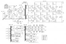
Just think that this old SEPP OTL tube amp schematic is very close to Mr. Pass F6 SS OTL amp concept .
Best Regards !
Attachments
buzzforb: I hope that ZM can arbitrate and resolve this question.You sure?
banat: you wrote in post #921
Just think that this old SEPP OTL tube amp schematic is very close to Mr. Pass F6 SS OTL amp concept .
Thank you for this valuable and exact input. It is truly very close to Conceptual F6. It goes to show that few things are new and novel under the sun! This schematic also implies that depletion JFETs and SIT devices can be readily used in Conceptual F6. Their biasing scheme is right there.
Best regards.
Very easy I think to do:
The output tubes then run in OLT style (or SEPP/circlotron style as some like it
- you can do it partly and retain the source follower of the input. The advantage of the Power (J)FET is the low drive voltage; a tube needs much more drive voltage. You might be able to use a Lundahl LL1674 (1:4). Try something like that.
).
Thank you for your valuable input. Very easy indeed as post#921 by banat showed. As you say in the underlined above, the front end can also be solid state [a la Pass or other] to make a hybrid power amp.
Best regards.
buzzforb. I need to understand circlotron which I will chase. Best regards.Apparently I am the blind alley
Love it!Hey Antoinel !
Just think that this old SEPP OTL tube amp schematic is very close to Mr. Pass F6 SS OTL amp concept .
Best Regards !

Notice the Phase dots on the Xfrmr! let's try to get all that strait...
buzzforb. I need to understand circlotron which I will chase. Best regards.
Maybe we should try to do a Ciclotron Design/Build thread??? Curiosity is building? The best of all N designs??? A transformer is a great input option??? It dosen't have to be the M.R./F5 looking circuit, Circlotron with gain, it can be the bridged source follower like an original...
OK... OK...
flg; Most important is that signals on the secondaries are out of phase with each other like that corrected by Mr. Pass in Conceptual F6. On the primary side, the phase dot is reversed relative to the phase of the upper tubes because of the inverting gain stage [first tube; absent in Conceptual F6] followed by the tube follower. I hope that I got it straight.Love it!
Notice the Phase dots on the Xfrmr! let's try to get all that strait...
oh boy .......
DiyA is full of Circlotron threads (best ones, I think - look for Atmasphere)
we really don't need that stuff here
besides - circlotron is a way to get rid of output xformer
for me - it's same as classic PP , just PSU's arranged in different , sans OT
input xformer is boiled water
output stage is beaten to death in Quad 303 threads on forum and around the web
what else ?
greatness of project is in simplicity and mix of few right old tricks , with new parts , but not in novelty
I'm happy because of F6 as little bunny in sex time , but lets have proper attitude - basic things must be learned outa thread
frankly - they're covered already few times in very thread
Last edited:
Thanks ZM. I'll check it out.oh boy .......
DiyA is full of Circlotron threads (best ones, I think - look for Atmasphere)
Hey Antoinel !
Just think that this old SEPP OTL tube amp schematic is very close to Mr. Pass F6 SS OTL amp concept .
Best Regards !
What an elegant design!
I have a 50 W Krohn Hite tube OTL Lab amplifier (20 kg/ch) , the effort they took to have constant phase angle over the 0Hz to 500 KHz range - it is mind boggling. And here it is just perfect and simple!
I stayed close to home by quickly reading the article "Build the Amazing FET Circlotron" by Michael Rothacher. The Atma-Sphere site was full of ads and no schematic. I also read the original 1954 paper by Wiggins. The attached file shows a very simplified schematic of the FET Circlotron [a la Rothacher] next to the output stage of Conceptual F6. They do not appear similar to me. FET Circlotron is a bridge and Conceptual F6 is not.oh boy .......
DiyA is full of Circlotron threads (best ones, I think - look for Atmasphere)
Attachments
Thank you buzzforb for the link.Don't know if this will help.
6C33C OTL
Last edited:
The Atma-Sphere site was full of ads and no schematic..
Antoinel
Here is the link to DIY Atma-Sphere M60 OTL Circlotron tube amp , there you can find the schematic ,altogether with many valuable blah - blah stuff , ( including mine blah - blah stuff ) : http://www.diyaudio.com/forums/tubes-valves/161112-what-tubes-tube-amp-2.html
BTW , if you want to make bias network for F6 Amp in the same way as is done on SEPP OTL Tube amp from mine previous attached schematic than .....
It is just my personal opinion that is important thing to succesfully DIY F6 SS SEPP amp to find Right relative main ( 60 Hz) AC phase status between this two equal independent & floating bias secondary coils on main PSU transf.
By reversing relative AC phase of this two independent secondary bias coils you can worse or improve Amp output power stage (SEPP) PSRR significantly .
Same is valuable for relative relation between output power stage (SEPP) PSU secondary power coil AC main phase and this two independent bias coils AC phases .
Best Regards !
Last edited:
- Home
- Amplifiers
- Pass Labs
- F6 Amplifier