I have a few SK1530/SJ201 FETs left from a balanced F5 build. I will give them a try. Of course, these parts are unobtainium. I also have some FQP19N20C and FQP12P20 FETs to try, but I prefer the TO-3P package to the TO-220.here are the Ciss charts from the datasheets - in both cases the P channel parts have higher capacitances compared to their n channel pairs but the toshiba complements look closer on paper. They appear flatter also.
What was the impact of [this dreaded] input capacitance on the power bandwidth before applying loop feedback?I have a few SK1530/SJ201 FETs left from a balanced F5 build. I will give them a try. Of course, these parts are unobtainium. I also have some FQP19N20C and FQP12P20 FETs to try, but I prefer the TO-3P package to the TO-220.
Thanks Zen Mod. Please show a clarifying schematic as your time allows. One may also consider a quasi P-channel complement of R100A [or other JFET] by compounding it with a leading small signal bjt; for example. Mr. Pass used quasi PNPs in older work you showed in a post of Papa's Pub's. It is less symmetric; but the input capacitance presented to the secondary windings is like that in diyF6.
lhquam. The article which is entitled "MOSFET Citation 12" at www.firstwatt.com shows the schematic of said power amp using a quasi complementary compound of PNP-IRF-100 in its power output stage.
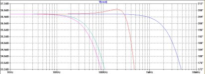
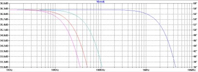
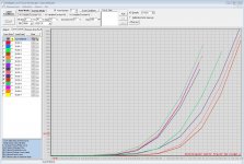
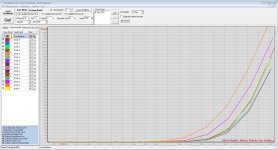
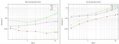
Here are two sets of the open-loop frequency response sweeps (using LTSpice) with different assumptions about FET and transformer capacitances. The two sets of sweeps are with(left) and without(right) cascoded outputs. The parameter Kc is multiplied by all FET capacitances. The parameter Ct is the transformer interwinding capacitance. The 4 sweeps are:What was the impact of [this dreaded] input capacitance on the power bandwidth before applying loop feedback?
Kc Ct
1 18nF violet "normal" caps
1 0nF orange only FET caps
0 18nF cyan only transformer caps
0 0nF blue no caps
With cascoding, the effect due to FET capacitances is greatly reduced and transformer capacitances dominate. Without cascoding, the we see the exact opposite - FET caps dominate.
Attachments
Sorry guys one step back to the SS F6....
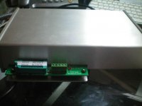
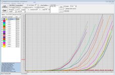
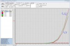
I got the curve tracer from locky-z here on the forum yesterday and played with it to cure my Semisouth problem...
here you see all my fund 8x R100 and 8x R125....
x-axis the Vgs, y axis Id
As you see they are all fairly different...at the first glance you can not separate R100 and R125....
(continued)
Attachments
Last edited:
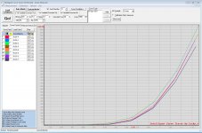
so i found some pairs....
left R125
right R100
it is so easy now!
and the best.... the pairs i found are more or less the same I got by solder and unsolder all the combinations and measuring the distortion by ARTA and other programs. This took endless hours.....!
So next days I will rebuild F6 and my J2 clone....
of course even the pairs have small transconductance differences and I will see how much distortion this will produce at 1kHz and what kind of phase I can get....
All very, very interesting!
Attachments
Last edited:

so i found some pairs....
left R125
right R100
it is so easy now!
and the best.... the pairs i found are more or less the same I got by solder and unsolder all the combinations and measuring the distortion by ARTA and other programs. This took endless hours.....!
So next days I will rebuild F6 and my J2 clone....
of course even the pairs have small transconductance differences and I will see how much distortion this will produce at 1kHz and what kind of phase I can get....
All very, very interesting!
hello generg. I hope that you do this simple experiment before you rebuild diyF6 to show the matching or not of its existing JFETs.
- Idle the amp to establish a steady state.
- No Load.
- Measure Vgs at a 0DCV output offset.
- Decrease the bias current of the amp by 0.3A. Establish a thermal steady state.
- Repeat step 3.
- Repeat steps 4 and 5 several times until the final bias current reaches ~50-100 milliamps.
- May need to insert a small power resistor in the drain circuit of the upper JFET to sense or measure current; like Mr. Pass did.
- Remove the old JFETs.
- Connect the matched JFETs.
- Repeat steps 7 to 1 by increasing bias current in 0.3A steps.
- Graph the results.

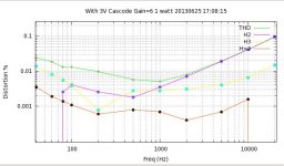
Sorry, I misread the colors on the cascoded plots. With cascoding H2 and >H3 harmonics are greatly reduced and much flatter curves. H3 increases at about the same rate, but at much lower overall levels.Here are sweeps of harmonics vs. watts at 1kHz into 8 ohms. Bias is 1.3A. No AC degeneration.
Left is with cascoding, right is without. Obviously cascoding reduces all harmonics, particularly H3 and higher.
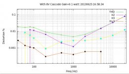
Here is an experiment is different cascode voltages. On the left is a 1watt THD sweep with Vds=3V on the drive FETs. On the right is a sweep with Vds=8V.
No significant difference.
No significant difference.
Attachments
it's begging for rails voltage decrease ; even if cascoded , I believe entire shebang will behave sweeter having more proper voltage across cascoded (active) mosfets
that's at least my experience with Jfets - in yore , when I compared Papa Borbely approach ( "voltage starved" ) vs. Papa approach (put them in sweet spot and cascode)
I am still trying to figure out what you intended to say here. Why do you say "rails voltage decrease"? Are you suggesting that I reduce Vds of the drive FETs below 3V? Without cascoding, these FETs do rather well at about Vds=20V to 30V. With cascoding at Vds=3V, I am seeing 5x-10x decrease in distortion. At Vds=8V I do not see any significant improvement. I did not even consider Vds=20V because that would double idle power dissipation.
Last edited:
I am not unhappy with the results I am getting. They are not as good as the simulations, but everyone has been warned that the Spice FET models are inadequate.Would ZenV8 be helpful. I know we are dealing with somewhat different animal, just guessing/grasping.
The parameter space for this amplifier is HUGE. I think my next tests will be with FQA12P20 and FQA19N20C FETs. Then I will try the 2SJ201 and 2SK1530 Toshiba (unobtainium) FETs.
- Home
- Amplifiers
- Pass Labs
- F6 Amplifier