you are saying that all your F6 will not be the same ?
or that all ours* F6's will not be the same ?

-Tea , Coffee ?
-Yes , please .....
The Coca Cola Kid - YouTube
* not mine , Bubba
or that all ours* F6's will not be the same ?
-Tea , Coffee ?
-Yes , please .....
The Coca Cola Kid - YouTube
* not mine , Bubba
With F6 and F5T trimed to similar distortion ratio at 1K, sou d is definitely unique to each design. I hate that SS fets dried up. This amp was going to be a great teaching tool for vlamp builders. F5 is trimmable, but doesnt seem to offer the range.
Suppose H2 and H3 are independent variables. There maybe a handle or a tweak [e.g. a Zen Pot] to increase and decrease %H2, and a second but different handle [?] which does not affect %H2; and also increases and decreases %H3 at will. Now I have the making of a two level factorial design leading to 5 experiments: A % THD analyzer is needed.
- H2 High and H3 High
- H2 High and H3 Low
- H2 Low and H3 High
- H2 Low and H3 Low
- H2 Center [(H+L)/2] and H3 Center.
So, does the design of F6 have two different "tweaking handles" to independently vary H2 and H3?
Thanks buzzforb, your answer is great news. Please specify which handle affects H2 only, and the other one which affects H3 only.
Best regards
Thanks buzzforb. The article on F6 by Mr. Pass has a wealth of info in a few paragraphs. I'll sort it out.Havent defined it that well but if you look back through the thread, hints are evrywhere.
Last edited:
Mr Pass's article in 6moons has a great explanation on the specific handle [degeneration and JFET matching] to manage H2 and its different manifestations. In lhquam's post #s 3184 and 3186 he separated H2, and H3 from Total %THD. For example, in post 3186 he compared simiulation with actual results on TEASER-6. At 500 Hz, He found H2 was ~0.008%, and H3 was ~0.005%.Thanks buzzforb. The article on F6 by Mr. Pass has a wealth of info in a few paragraphs. I'll sort it out.
Truly low H2 and H3 numbers for TEASER-6. Suppose one operated diyF6 in Class AB mode. Will its comparative H2 and H3 be much higher? Will more H2 and/or H3 translate to better sonics.
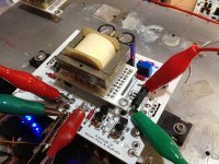
I completed F6 with IRF240's.
I used 1R Source resistors. The bias only went to ~500mv with existing 5K Pot.
Assuming I go, to .5R resistor, I think this will give me enough room to bias higher. I was too scared to add pots across the source resistor. With IRF240's I am not sure if that's a good idea, assuming the overall source resistance goes below <.5R overall.
If not I was considering changing R3-4.
Any thoughts?
Attachments
Thanks to Tea-Bag for his high caliber supplies; R100A and the upcoming PCBs. I am slowly following your recommendation.nothing is stopping you from testing it
LED voltage is culprit
what you're using - blue ones , how many in series ?
and - what voltage you're getting across them ?
ZM - did not even think of that! The only thing Papa asks us to measure
")
It's 4.05v using one blue and one red Led. I will try two blue ones.

nothing is stopping you from testing it
Zen Mod. Here is what astounds me by using this example:
- 0.1% H2 is 1 sine cycle of H2 in 1000 sine cycles of the fundamental H1.
- The amplitude of one H1 in a reference 2.828 Vrms into 8 Ohms [or 1 W] is equal to (2.828 /1000) = 0.00283 Vrms.
- If the amplitude of one H2 cycle is equal to that of one H1 cycle, then the answer is 0.00283Vrms across the same 8 Ohms simultaneously stimulated by H1.
- What is the output power attendant to H2?
- P{W} = [V X V]/8 = 1 microWatt.
- But fortunately; human hearing is 1000 times more sensitive in detecting H2 than H1 [just playing with working numbers].
- Thus, the actual output power from H2 is 1 milliWatt.
ZM - did not even think of that! The only thing Papa asks us to measure
It's 4.05v using one blue and one red Led. I will try two blue ones.
Two Blues give room to bias up much higher. Measures closer to 4.25v now.
I just used two random IRF240's, no matching tried. Offset still good. I will try some matched Fairchilds in the other channel.
Good looking boards. Yup - you need to put LEDs in series or use zener diodes up around 6 volts.
I completed F6 with IRF240's.
I used 1R Source resistors. The bias only went to ~500mv with existing 5K Pot.
Assuming I go, to .5R resistor, I think this will give me enough room to bias higher. I was too scared to add pots across the source resistor. With IRF240's I am not sure if that's a good idea, assuming the overall source resistance goes below <.5R overall.
If not I was considering changing R3-4.
Any thoughts?
- Home
- Amplifiers
- Pass Labs
- F6 Amplifier