I use R = 0R68 in combination with C = 44000uF.
That gives a first order filter with a corner frequency of 5.3Hz.
The ripples are at 100Hz fundamental.
So the attenuation is about 19x.
Using the same C with 0R12 gives a corner frequency 30Hz, or 3.3x ripple reduction.
You can always increase C to compensate for that.
As said in post#1, many way to skin a cat.
Patrick
I use R = 0R68 in combination with C = 44000uF.
That gives a first order filter with a corner frequency of 5.3Hz.
The ripples are at 100Hz fundamental.
So the attenuation is about 19x.
Using the same C with 0R12 gives a corner frequency 30Hz, or 3.3x ripple reduction.
You can always increase C to compensate for that.
As said in post#1, many way to skin a cat.
Patrick
what is the formula for calculating that?
Patrick,
I assume that the use of the C-R-C in place of the C-Reg-C, may benefit from better "C's". What caps do you suggest for this section of the circuit?
There are quite a few of these in the build (8/channel - I think) and maybe a GB would lower the cost very significantly. To match the rest of the build I would go for the best")
Cheers,
Nic
I assume that the use of the C-R-C in place of the C-Reg-C, may benefit from better "C's". What caps do you suggest for this section of the circuit?
There are quite a few of these in the build (8/channel - I think) and maybe a GB would lower the cost very significantly. To match the rest of the build I would go for the best
Cheers,
Nic
I use R = 0R68 in combination with C = 44000uF.
That gives a first order filter with a corner frequency of 5.3Hz.
The ripples are at 100Hz fundamental.
So the attenuation is about 19x.
Using the same C with 0R12 gives a corner frequency 30Hz, or 3.3x ripple reduction.
You can always increase C to compensate for that.
As said in post#1, many way to skin a cat.
Patrick
The C's in both CRC and CRegC are the same on the same PCB. I think there has been extensive discussion about the possible choices at the old Balanced F5 thread. I do not have a real preference, and we use Panasonic 105°C snap-in electrolytics from Digikey for our proto. But anything from EPCOS (Siemens), Panasonic, BC Components, ... should be good. Maybe an additional MKP 2.2uF in parallel to the last C.
I don't belong to the school of trying 20 different caps at every position of the circuit and decide by subjective impression which one has what signature. One of you would have to take over that task for me.
Patrick
I don't belong to the school of trying 20 different caps at every position of the circuit and decide by subjective impression which one has what signature. One of you would have to take over that task for me.
Patrick
Starting from here and lots of discussions that followed :
http://www.diyaudio.com/forums/pass-labs/172770-balanced-f5-question-14.html#post2393999
Patrick
http://www.diyaudio.com/forums/pass-labs/172770-balanced-f5-question-14.html#post2393999
Patrick
A qualitative discussion of CRC vs CRegC :
http://www.diyaudio.com/forums/grou...e-user-distribution-check-12.html#post2791748
See also :
http://www.passdiy.com/pdf/zen-ver3.pdf
Patrick
http://www.diyaudio.com/forums/grou...e-user-distribution-check-12.html#post2791748
See also :
http://www.passdiy.com/pdf/zen-ver3.pdf
Patrick
No fixed rules, just what I feel like.
Normally around 1/1000 to 1/20000 of the main C.
A good reference :
http://sound.westhost.com/power-supplies.htm
But feel free to experiment.
Patrick
Normally around 1/1000 to 1/20000 of the main C.
A good reference :
http://sound.westhost.com/power-supplies.htm
But feel free to experiment.
Patrick
Last edited:
A large capacitance has a large paracitic resistance and inductance in series with it. Adding a smaller capacitor improves the Power supply's high frequency response. A value of between 1uF and 10uF is appropriate after the reservoir capacitor. In high speed digital logic at least a 100nf cap should be plased next to each IC. With several such caps and several pF range caps also often being added.
Bipass caps often produce complicated higher freq resonances, so you sometimes have to consider adding specific value 'snubber' ccts (R-C) to the paralleled capacitors to get the best results.
Fortunately, some combinations seem to work okay without the extra damping/filters but many don't - plenty of source material available about 'snubber' design, and other threads here, too.
Fortunately, some combinations seem to work okay without the extra damping/filters but many don't - plenty of source material available about 'snubber' design, and other threads here, too.
In high speed digital logic at least a 100nf cap should be plased next to each IC. With several such caps and several pF range caps also often being added.
While completely off-topic, I found the following recent article to be a nice illustrative write up of this,
Decoupling by Example
It seems that during a recent 74xx TTL contents, many of the entrants lacked use of bypass capacitors....
Dan
Just a teaser from the test team.
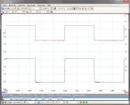
Smyslow sent me a square wave response of his F5X proto currently using 2SK1530 / 2SJ201 output devices, and 2SK170 / 2SJ74 front end cascodes.
Red is input; blue is output.
Fitzfish, meanwhile, also has his standard grounded X measured with some excellent distortion results.
But I'll leave him with the honour to tell you.
So we are making progress.
Patrick
Attachments
Last edited:
Thanks Patrick.
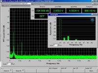
It is exciting to see them working. I'll start with a taste of the measured performance and promise to post many more in the upcoming build thread.
This is THD in the grounded X configuration, 1W into 8 ohms. After some additional testing I'll be switching to floating X.
The total harmonic distortion is around 0.0006%.
More to come!
Dave
Attachments
- Status
- This old topic is closed. If you want to reopen this topic, contact a moderator using the "Report Post" button.
- Home
- Amplifiers
- Pass Labs
- F5X -- the EUVL Approach