I have another piece of good news for you. ")
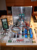
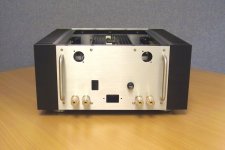
A test team member has his proto fired up and working.
So the PCBs should be OK, thanks to Dave's immaculate work.
I shall release them next weel to the forum so that you can pre-order.
As you can see he is not using the current limiting circuit.
He is also on a special mission to test other output devices other than 2SK1530/2SJ201.
Distortion measurements next week if he can find time.
Herzlichen Dank Uwe.
The schematics of the standard circuit will be released once it has been tested.
I am busy arranging that right now.
Greg, please kindly get in touch by email.
Patrick
Attachments
To give you another update :
I have seen the machined parts (before anodising).
They are of a sufficiently high quality that I would have accepted them for my own use.
And I am known to be demanding.
We have test anodised one set of parts and found some cosmetic issues with the front panel.
The cause is still under investigation.
We do not believe it is to do with our process, but it might be a material problem.
A new panel is being test anodised in the next couple of days to see if the same occur.
Any such parts will be rejected at our costs.
It only means a delay for you, for which we apologise.
Some of these issues only show up after anodising.
It is impossible to tell during the machining stage.
Patrick
To give you another update :
Any such parts will be rejected at our costs.
Patrick
Hi Patrick,
Thanks.
Mark & I spent the most of today to put one of the Gb F6\5X Case parts together.
The good news is that there is neither design nor manufacturing errors.
Everything fitted perfectly. And the appearance turned out as we expected.
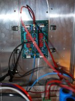
The vibration isolated cradle can also be locked and unlocked as planned.
Wiring space is tight, but not as tight as I initially thought.
So I declare myself more than happy with what we are offering you.
As said, I would not hesistate to use it myself, which is the standard of acceptance.
Patrick
The good news is that there is neither design nor manufacturing errors.
Everything fitted perfectly. And the appearance turned out as we expected.
The vibration isolated cradle can also be locked and unlocked as planned.
Wiring space is tight, but not as tight as I initially thought.
So I declare myself more than happy with what we are offering you.
As said, I would not hesistate to use it myself, which is the standard of acceptance.
Patrick
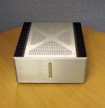
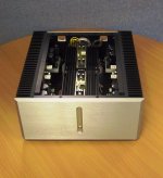
We are going to take you through the assembly, starting from the finished product, and removing parts to review the inside, one by one.
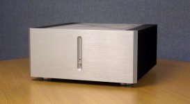
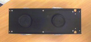
Starting with the overall views.
Only the few screws on the top are visible, and nothing protruding above the metal surface.
This is only possible when the machining tolerances are tight enough.
Patrick
Starting with the overall views.
Only the few screws on the top are visible, and nothing protruding above the metal surface.
This is only possible when the machining tolerances are tight enough.
Patrick
Attachments
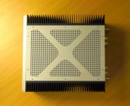
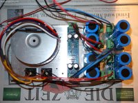
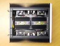
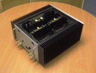
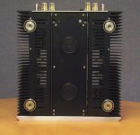
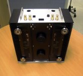
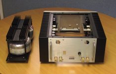
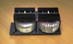
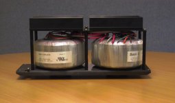
Removing the top plate to show the components inside.
Overall wiring not completed yet.
Amplifier modules, Capacitor modules, Regulators are all clearly visible.
Patrick
Overall wiring not completed yet.
Amplifier modules, Capacitor modules, Regulators are all clearly visible.
Patrick
Attachments
- Status
- This old topic is closed. If you want to reopen this topic, contact a moderator using the "Report Post" button.
- Home
- Amplifiers
- Pass Labs
- F5X -- the EUVL Approach