Thank you for this careful explanation Dave.
Hi Nic,I think to have understood that if one is in the lucky situation of having sufficient FETs to pick from, one can "simply" do SK170/SJ74 Idss matching with 5R degeneration for the SJ74. Is this correct?
Cheers,
Nic
My pleasure. Very nice to see some activity here after such a long time. Hope to see more once FETs are available!
The intent essentially was the opposite. As Patrick points out a single point match for all devices should be the absolute minimum for each quad. Pick the Idss for the K170s and J74s as listed in the table and use the 5R resistor. These are datasheet values and get you close enough, bare minimum quality of match. This would apply mostly to those who are buying JFET sets from a vendor pre-matched.
If you have many JFETs to choose from build a fixture similar to the one described with resistors and jumpers or switches and do the three point match.
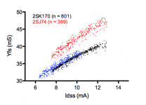
I took it a step further and did curve matching on the input devices to closely match what Patrick had previously done. I chose devices initially on static Idss based on the chart then ran curves on each group. I matched N/P sets with the best curves. Once matched I adjusted the resistor for the J74 for best Idss balance in circuit. Achieved near perfect curve matches but had to look through several date codes of each and many transistors of similar Idss to find them. Considering I did only 5 point matches on the output devices and had a limited number to choose from, the front end matching may have been overkill...
Dave
One more point - The K170s were more consistent as far as true curve matching goes. Even lot to lot they were pretty close when testing within a given Idss range.
The J74 were more varied, even within the same date code. Probably more time (and possibly devices necessary to choose from) needed here if doing true curve matches.
This data is from a fairly limited sample set. 3-4 date codes each and only few hundred total curve tested once selected for Idss in the correct ranges. This may not be represenative of parts you have...
Hope it helps,
Dave
Hi Dave,
I hope you will indeed see some more action here in the not so far future.
I should have a nice heavy MOSFET package from Davide landing my desk tomorrow
The K170/J74 is more a private thing as I don't want to run out of these useful quasi unobtanium FETs in the near future.
You write: "Once matched I adjusted the resistor for the J74 for best Idss balance in circuit.". Will this not also affect the matching? Does that mean that every J74 requires a different resistor value
Anyway, I'm sure that I will understand a lot more once I have done a few thousand measurements
Cheers,
Nic
Hi Nick,
Good questions.
IMPORTANT NOTE*** - don't overlook the fact that the 5R resistor suggestion from the chart is specifically for the 6.5/7.6mA combination. If the Idss for your matched sets are 8/8.9mA, for example, the datasheet values would dictate 3R3 ohm Rdegen, not 5 ohms. Consult the chart for a good starting value of Rdgen based on the Idss parts you have.
As I said, I measured the static Idss without any Rdegen (maybe this point was not clear) to sort what I have into Idss groups. Only then proceeding to use the chart for an Rdegen starting value. Once in the ballpark either use the enhanced version of this fixture for 3 point matching (with the extra resistors to fine tune things) or curve match with the same type of selectable Rdegen resistors in the fixture.
If you have to you can fine tune the Rdegen resistor on the board after assembly while dialing it in (as see here) to fine tune the bias balance of the front end top to bottom before the output devices are installed.
Not sure it is clear but once you work through it, it should become more so…
Dave
Good questions.
Will this not also affect the matching?
Possibly, though maybe for a different reason than you expect - The best curve matches N-to-P I found did not follow Patrick's chart exactly for Idss. That chart is based on "typical" characteristics from the datasheet. Real parts will vary some from these "ideal" characteristics. My best sets were also slightly lower Idss ratio N-to-P so to get the best matched P/N devices and to achieve good current balance once in circuit I needed 4R degen resistors.Does that mean that every J74 requires a different resistor value
IMPORTANT NOTE*** - don't overlook the fact that the 5R resistor suggestion from the chart is specifically for the 6.5/7.6mA combination. If the Idss for your matched sets are 8/8.9mA, for example, the datasheet values would dictate 3R3 ohm Rdegen, not 5 ohms. Consult the chart for a good starting value of Rdgen based on the Idss parts you have.
As I said, I measured the static Idss without any Rdegen (maybe this point was not clear) to sort what I have into Idss groups. Only then proceeding to use the chart for an Rdegen starting value. Once in the ballpark either use the enhanced version of this fixture for 3 point matching (with the extra resistors to fine tune things) or curve match with the same type of selectable Rdegen resistors in the fixture.
If you have to you can fine tune the Rdegen resistor on the board after assembly while dialing it in (as see here) to fine tune the bias balance of the front end top to bottom before the output devices are installed.
Not sure it is clear but once you work through it, it should become more so…
Dave
Last edited:
This is of course fine tuning to the last 1% perfection, Dave.
For most DIYers who already have matched FETs according to the table I published, you can set the value of the degen resistor for the J74 as follows :
Measure Id of the 2SK170 using a degeneration resistor of 11R, as the JFET will actually see in the circuit. Note down this Id (Drain Current) value.
Using a 20R trim-pot as degeneration resistor for 2SJ74, repeat the same Id measurement. Note reversed power supply polarity of the P-JFETs.
Adjust the trim-pot until you get the same Id as the 2SK170s with 11R degeneration.
Measure and note down the resistance of the trimpot.
Subtract 11R from this value will give you the R_degen value for the J74s (nominally 5R).
Use the nearest standard value you can get for R_degen. Don't worry if it is not perfect.
Any imperfection will slightly increase second harmonics on one half of the circuit (Single Ended F5) which will then be cancelled by the balanced circuit.
That is the beauty of the X.
Of course you can also follow the fine tuning action of Dave for 100% perfection, but you need to know what you are doing.
Patrick
Last edited:
I should correct myself first.
The 11R quoted in Post #145 should have been 9.1R (9.167R if you wish to be 100% accurate).
Forgotten to take into account the 55R feedback resistor as well.
Why did I say this is the last 1% pefection :
A K170 has an effective source resistance (= 1/ Yfs) of about 30R, and varies a bit with actual Id.
A J74 has about 25R. Hence we add 5R degen extra. It also varies a bit with Id, by about the about same amount.
But since this is degenerated in the circuit also by the feedback network, the total eq R_source is then 30+9.167 ~ 40R.
Dave mentioned that in the perfect situation, you might wish to use 3R3.
This is a delta of 1.7R from the nominal value.
But seen in the circuit, it is 1.7R / 40R = <5%.
And that is difference in open loop gain between top and bottom halves.
Further reduction is then given by negative feedback, and balanced topology.
Patrick
Of course your 5R1 value was chosen for a reason like most things you do
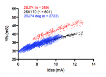
For my FETs I actually find 5R6 and 6R2 to be a bit better. As computing cost little I in the end actually used 7 different Rdeg (4R3, 4R7, 5R1, 5R6, 6R2, 6R8 and 7R2) to generate a virtual set of 2723 degenerated 2SJ74's (see figure) and used these for matching. With those I obtained 42 NNNNPPPP-sets with 0.5% tolerance for both Idss and Yfs. This is a yield of about 43% for the 2SJ74.
Of course there is the downside that each 2SJ74 will need a different Rdeg. But as a DIY'er I can live with this minor logistic complication.
Obviously Oneclock has measured matches while mine are calculated and should to be verified experimentally. I nevertheless trust the practical validity of the equations some kind person provided me with
Where is that F5X Pre?
Cheers,
Nic
P.S. Note how increasing Rdeg pushes both Idss and Yfs down posing a limit to what can be achieved in terms of matching. Using 100 different Rdeg's values would in fact not increase yield notably. Many 2SJ74 will never match because they have to low Idss.
Attachments
Get some 2SK170GRs.
I didn't think about that. You never run out of solutions do you
Nothing exciting.
Not excited. Just learning from others experience.
Of course your 5R1 value was chosen for a reason like most things you do
Of course there is the downside that each 2SJ74 will need a different Rdeg. But as a DIY'er I can live with this minor logistic complication.
Practically it's not a big deal, we just have to stock few resistors of these values, costs around 2 euros.
D.
- Home
- Amplifiers
- Pass Labs
- F5X -- the EUVL Approach - The Build Thread