You can check the accuracy by putting in ice water and then in boiling water, as Scott suggested.
You should get somewhere close to 0°C and 100°C.
Google triple point of water, even at home you can get better than .1C with a little care. It is considered the reference standard for thermometry and NIST has instructions for getting .001C. We did all this to qualify AD590's for the space shuttle. Review the history of the heat shield on the shuttle and you will get a harsh lesson on the value of obsessive measurement.
")
T4A on a 220Vac mains supply allows a 900VA transformer to be used. What size of transformer did you buy?........... should I reduce the fuse rating to 4amp slow blow as well? I'm about to close up the chassis.
Spec was 2x 600VA.
Gnd connection depends on you total system.
But you can take a look at this :
Earthing (Grounding) Your Hi-Fi - Tricks and Techniques
And of course the article from Bruno.
The G word: How to get your audio off the ground | EDN
(Read the entire article consisting of multiple parts.)
Patrick
Gnd connection depends on you total system.
But you can take a look at this :
Earthing (Grounding) Your Hi-Fi - Tricks and Techniques
And of course the article from Bruno.
The G word: How to get your audio off the ground | EDN
(Read the entire article consisting of multiple parts.)
Patrick
Do I need to connect the input's gnd to the chassis gnd? Also, since my bias is around 0.230v, should I reduce the fuse rating to 4amp slow blow as well? I'm about to close up the chassis.
T4A on a 220Vac mains supply allows a 900VA transformer to be used. What size of transformer did you buy?
If that is what Pmc bought then Pmc needs two T3.1A mains fuses. Fuse each transformer separately. You can choose to have a single mains fuse earlier in the power circuit and the single common fuse should be around T6A, or T8A.Spec was 2x 600VA............
There were smoke coming out of the left channel. Somehow, I think the wire connection isn't right. Right now I put a 40w bulb between the amp and the main power. The light dimmed when I push it to the standby mode. The current dropped at the main 24vdc to the finder relay.
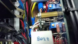
I connected the gnd from the input board to the chassis gnd. Somehow, it is connected to the (-) output of the amp. Is this so? I thought it was supposed to be floating.
Input ground > amp ground > disconnecting network or CL-60 or similar > chassis/earth ground.
(-) and (+) outputs might be connected to amp ground via 220Ω (R21 & R22), if you chose to use it.
Attachments
Last edited:
Input ground > amp ground > disconnecting network or CL-60 or similar > chassis/earth ground.
(-) and (+) outputs might be connected to amp ground via 220Ω (R21 & R22), if you chose to use it.
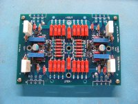
Yes, I used the R21 and R22 resistors. Should I remove these or should I just remove the CL-60 thermistors?
> Yes, I used the R21 and R22 resistors.
No, they have nothing to do with your problem.
Everyone, including me, used them and we have no problems.
> Should I remove these or should I just remove the CL-60 thermistors?
None of the above.
You have a short of your output to Gnd, according to you.
I would first check that, e.g. whether the Drains of your MOSFETs are touching the heatsink electrically.
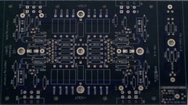
> I just noticed there are 2 smd capacitors between the trim pots.
Optional, and you should not have soldered the electrolytic cap if you are not using cascode, as shown in your photo.
I suggest you do your testing with lab power supplies with current limit.
And you should short the inputs to Gnd during testing.
Patrick
No, they have nothing to do with your problem.
Everyone, including me, used them and we have no problems.
> Should I remove these or should I just remove the CL-60 thermistors?
None of the above.
You have a short of your output to Gnd, according to you.
I would first check that, e.g. whether the Drains of your MOSFETs are touching the heatsink electrically.
> I just noticed there are 2 smd capacitors between the trim pots.
Optional, and you should not have soldered the electrolytic cap if you are not using cascode, as shown in your photo.
I suggest you do your testing with lab power supplies with current limit.
And you should short the inputs to Gnd during testing.
Patrick
- Home
- Amplifiers
- Pass Labs
- F5X -- the EUVL Approach - The Build Thread