I am quite sad to hear that you have had problems. You and alazeira (I hope I spelled that right) have seemed to have a problem with the package being sent. As your package was sent by regular mail plus postal insurance I do not have a tracing number, I have got in my files lodgement stubs which I am going to use to try to claim insurance the moment I can open the box that contains them (I just moved again). I have most of enough parts here on my desk waiting to resend both your orders. By way of compensation If you would like I will solder one board each here and test it for you, with the modifications already done, and use this task to make an instructional video for all the rest. Otherwise I can send them as is and wait a little time myself. I will send this by courier at my expense, however it will take me about 1 week to solder and test them. Would you find this acceptable.
I am happy to give you my final PCBs as a part of this at no cost to you, if I need more I will do a small run myself.
P.s I know that you ordered two kits and will of course send you annoy her kit with the completed board, also I will send you two free LEDs on top of those in the kit as these are the hardest parts to obtain and you may find them useful as spares.
He promised in a week that sent my kit ...
A month passed and the man disappeared again.
No reply to mail, do not respond to the message.
Ashaw , not want anything from you!!
You can keep and money, you can keep the 2 kits!
6 months of waiting, I'm tired!
This time I also agree.
Zero response to emails, etc. And too many empty promises.
We have not received the second part of the article, so I shall write a test procedure.
Will take a couple of weeks, since extremely busy at work.
In the meantime, if there is anything we can help, please let us know.
I presume you have protection PCBs already.
Patrick
This time I also agree.
Zero response to emails, etc. And too many empty promises.
We have not received the second part of the article, so I shall write a test procedure.
Will take a couple of weeks, since extremely busy at work.
In the meantime, if there is anything we can help, please let us know.
I presume you have protection PCBs already.
Patrick
Unfortunately I am in the same situation as Vitalica with regards to Alexis (PCB but no parts). As I understand it, Greg says he has a couple extra kits, so perhaps we could purchase from him.
All components are available from Digikey or Mouser.
So other than the PCB there is no reason why you have to buy a "kit".
The only argument for a GB was to save money.
Or am I missing something ?
Patrick
Well, there is also convenience
Adding multiple items to carts, multiple vendors, backorders, minimum amounts, as well as the occasional confusion as to exact part#...In the end, though, I'm still hoping Alexis will come through. I would hate for this to be my first bad experience in dealing with a member on this forum.
Last edited:
Each channel has two totally separate Tx secondaries, recitfiers and CRCs (total 4x).
Each of these makes up a single unipolar power supply.
If you now connect the output to a 4R load, you should get very close to 16V 4A.
There is no reason why you cannot test them totally independently of each other.
So I don't really understand your question.
Perhaps you want to draw a schematics, for yourself and those who might help you.
Patrick
I was confusing myself last night, and was measuring across the wrong points. After giving the PS about 10 min to stabilize, I get +/-16.9V and 4.1A through my 8ohm load resistor. You are right, those Fukushima 1ohm resistor do get hot. I am measuring around 140-145 degrees C in my setup.
> if the power resistor casing is @ ~140ºC, what is the temperature of the wire element?
No idea, but since the case is likely to be Alumina, I would guess less than 200°C.
> What effect does that temperature have on the resistance?
I am sure an experience DIYer as yourself knows that Ni-Cr used in most power resistors can operate to 1200°C.
We are quite a bit away from that.
Most power resistors of such types are specified at ambient temperature rather than case temperature.
The ambient temperature between the the MPC74s on the CRC PCB is less than 100°C as Mark has measured in his amp.
According to the manufacturer's data sheet, it will still be able to operate at 80% of the rated load, i.e. 4W.
For a 0R22 operating at 2A, the dissipation is 0.88W.
We are still over-designing a factor of 4.5.
I consider that to be more than sufficient margin, even for industrial use requiring high reliability.
http://www.fu-futaba.co.jp/wp-content/themes/futaba/images/PDF/001.pdf
Patrick
Last edited:
The resistors supplied by us were MPC74 1Rs for use in the CRC power supply.
A set of 6 together made up 0R67 30W.
They were measured at room temperature at bias current.
So even if there were 6% change , this corresponds to 0.16V difference in the 16V rail voltage.
I do not consider 0.2V rail voltage deviation to be critical, do you ?
For the 0R22 resistors used in the amp itself, the ones supplied by us for batch 2 are tested at bias (2A).
They are inside the ventilated case, with temperature inside about 45°C, or 25°C above ambient.
The tempco given by the manuafcturer is actually a tolerance of +/-350ppm/°C.
Datasheets say Ni-Cr are 110ppm/°C or below.
So I also don't see any issues.
If you want even lower tempco, for perfection's sake, you may use Isabellenhuetten Manganin.
They have 15ppm/°C, costs 5 time more, and require heat sinking.
Patrick
F0r the sake of comparison, Caddock MP930 0R22 is specified at 200ppm/°C.
http://www.caddock.com/Online_catalog/Mrktg_Lit/MP9000_Series.pdf
Patrick
http://www.caddock.com/Online_catalog/Mrktg_Lit/MP9000_Series.pdf
Patrick
When testing the +/- voltage of the PS under load, do we need to temporarily ground the star ground point to get proper readings? The PS with an 8 ohm load is hovering right at 4A, but I'm not getting very useful +/- voltage readings.
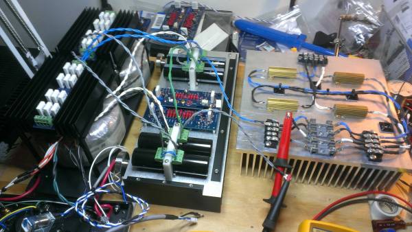
I was confusing myself last night, and was measuring across the wrong points. After giving the PS about 10 min to stabilize, I get +/-16.9V and 4.1A through my 8ohm load resistor. You are right, those Fukushima 1ohm resistor do get hot. I am measuring around 140-145 degrees C in my setup.
if the power resistor casing is @ ~140ºC, what is the temperature of the wire element?
What effect does that temperature have on the resistance?
and what is the resistance correction for the guesstimated temperature rise?
175degrees of rise times 350ppm gives more than 6% change in resistance.
Then add on the cold temperature tolerance.
What resistance did you actually test at?
Euvl, you are on a different tack.The resistors supplied by us were MPC74 1Rs for use in the CRC power supply.
A set of 6 together made up 0R67 30W.
They were measured at room temperature at bias current.
So even if there were 6% change , this corresponds to 0.16V difference in the 16V rail voltage.
I do not consider 0.2V rail voltage deviation to be critical, do you ?
For the 0R22 resistors used in the amp itself, the ones supplied by us for batch 2 are tested at bias (2A).
They are inside the ventilated case, with temperature inside about 45°C, or 25°C above ambient.
The tempco given by the manuafcturer is actually a tolerance of +/-350ppm/°C.
Datasheets say Ni-Cr are 110ppm/°C or below.
So I also don't see any issues.
If you want even lower tempco, for perfection's sake, you may use Isabellenhuetten Manganin.
They have 15ppm/°C, costs 5 time more, and require heat sinking.
Patrick
Horio is checking voltage and current.
What resistance is Horio actually testing with?
Is the result 16.9V @ 4.1A, or is it actually something else?
Does it matter now that Horio has a voltage he can rely on, whereas he started by saying
The PS with an 8 ohm load is hovering right at 4A, but I'm not getting very useful +/- voltage readings.
Last edited:
- Home
- Amplifiers
- Pass Labs
- F5X -- the EUVL Approach - The Build Thread