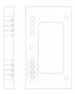
I did some drafting. A 10mm, 120 degree drill, may be barely to do the job if you cut the solder very short.
Of course 90 degree CSK tool is better. Or you can grind the 10mm drill to 90 degrees if your have a grinder.
Caution! It's dangerous to hand drill a 10mm on a plastic. You need very slow spindle speed and steady hand. Otherwise, you may drill through the whole nylon easily.
Mark
Of course 90 degree CSK tool is better. Or you can grind the 10mm drill to 90 degrees if your have a grinder.
Caution! It's dangerous to hand drill a 10mm on a plastic. You need very slow spindle speed and steady hand. Otherwise, you may drill through the whole nylon easily.
Mark
Attachments
Last edited:
New PCB is the easiest, but also most expensive. Also Jan already soldered, so no option for him.
Since the PCBs are from a GB I can only accept partial responsibility (that I did not spot the mistake in the Gerber).
But spotting the difference between 25mm & 28mm by naked eye is a bit beyond the average visual capability.
So we'll have to charge say 50% cost (cap boards only) plus postage if you want new PCBs, unfortunately.
I am happy to pay full cost + shipping and do any leg work if needed. I would not like to see you loose any more money that you already have on this project, I consider the case itself as a bargain as it is.
I am an attention to detail freak and quite fussy, if the extra yards need to be made I’d like to take them
")
Not mention my terrible drilling skills...
Last edited:
John,
You could be of great help of you could :
1) start a thread at GB to see how many Batch 1 subscribers (exclusively) would want PCBs,
and if so completely new set or only cap boards; this will help us estimate cost;
2) volunteer to do Alpha testing, so that we avoid such mistakes again.
Cheers,
Patrick
BATCH 1 PCB GB
People interested in new PCB’s there is a GB thread:
http://www.diyaudio.com/forums/grou...ted-batch-1-subscribers-only.html#post3262264
Patrick as for 2) I’m not comfortable or confident. Sorry.
People interested in new PCB’s there is a GB thread:
http://www.diyaudio.com/forums/grou...ted-batch-1-subscribers-only.html#post3262264
Patrick as for 2) I’m not comfortable or confident. Sorry.
I just used a craft knife to check how easily the Delrin cuts, by hand.
It was very easy to cut a chamfer around the one side that requires the clearance for the soldered tags sticking through the PCB.
Each of the 8 delrin holes were "moved" towards each other. I started with a 1.5mm wide chamfer, not quite enough. Then added a second cut increasing the chamfer to 2mm wide. Now the gaps are sufficient to allow the PCB to tight fit against the PCB.
But I found the 3 mounting holes did not quite line up.
this required the hand cut, one sided, chamfers to be extended to cut on the side of the holes towards the middle of the delrin.
Now the holes all line up and the PCB lies flat.
BTW,
I started with the PCB that had the smallest protusion on the solder side. This needed only that first stage of 1.5mm chamfer for the tight fit.
When I tried the PCB with what by my standards are enormous soldered pads then I found the extra cuts to 2mm and towards the middle were required.
It would appear that the way you solder will determine how much of the delrin needs to be removed.
I can confirm that the delrin cuts easily with a sharp craft knife. Mine is about 40years old on it's original blade that I resharpen occasionally with a stone or diamond hone, (not nearly as sharp as a new carpet knife blade).
Another BTW,
a carpet knife blade has a tip that is machined to 45degrees. This shape will make it more difficult.
I used a blade where the tip is cut to ~30degrees.
Last edited:
You can have the nylon pads - I will take the boards with pre-soldered caps and terminal blocksI'll take the throw always......to save the environment.
Handverzinker WOLFCR.4315 | Kieft IJzerwaren / Gereedschap B.V. Putten, Webshop
I happened to have this tool. Not sure how to name in it in English. Using this it takes about 15 secondes per hole to adjust it so that the pcb sits perfectly flat on the surface.
Problem solved!
I happened to have this tool. Not sure how to name in it in English. Using this it takes about 15 secondes per hole to adjust it so that the pcb sits perfectly flat on the surface.
Problem solved!
This is a manual countersink tool.
You can also get one of these and use a battery powered drill to do the same.
Browse the Drill Bits - Countersink department at Aubuchon Hardware
Countersink Drill - 13mm General Use
As you said, 15 seconds.
Please kindly show them a picture of the results.
Patrick
You can also get one of these and use a battery powered drill to do the same.
Browse the Drill Bits - Countersink department at Aubuchon Hardware
Countersink Drill - 13mm General Use
As you said, 15 seconds.
Please kindly show them a picture of the results.
Patrick
I bought a 13mm (1/2") countersink bit from a local hardware store for $5, and it works like a charm. With my hand drill, it took about 3-4 mine to countersink the holes. The boards fit nice a flush now.
An externally hosted image should be here but it was not working when we last tested it.
GB builders,
There have been a couple of additional errors discovered in the BOM recently. I would like to ask the GB builders with boards to review the BOMs and other documentation to see if any other errors can be spotted before we update the BOM again. We have had a few pair of eyes on it during development but are often too close to things to see some of the mistakes that would otherwise be common sense to us.
I will wait a few days to see if anything else pops up then post.
Thanks,
Dave
Maybe an additional BOM can be established for the elements shown in the wiring schematics of the whole amp (AUX transformer, current limiters and fuses for different mains voltages, relays, ...):
http://www.diyaudio.com/forums/pass-labs/183362-f5x-euvl-approach-71.html#post2959552
I do have a couple of questions related to the circuit shown above:
- What type of fuse and fuseholder do you recommend for the AUX circuit?
- How (where) should this fuseholder and the Finder 46.61.9/24V relay be mounted?
- Home
- Amplifiers
- Pass Labs
- F5X -- the EUVL Approach - The Build Thread