Just go ahead and start to build a F4 V2 or V3. Both trasformers and heatsinks will suits very well. Connect each secondary to own dedicated Graetz bridge, as Zen Mods says, and there will not be any trouble using the transformer as is. With more than 2x40V DC, you should be able to have 100W classe A. If the heatsinks can tolerate a bias of 2.4 A, you have a 100W "match". Let the temperature on the heatsinks "decide", but let the amplifier works for hours before you decide the bias. A very "silent" fan is also a good idea. I have used Noctua NF-F12 with good results.
Eivind Stillingen
Eivind Stillingen
Just go ahead and start to build a F4 V2 or V3. Both trasformers and heatsinks will suits very well.
Unfortunatly the F4 PCB's are 250mm long, If I want to use these heat sinks in this chassis, the heat sinks must be mounted independantly, as shown in my previous post. And they are only 190mm long. http://www.diyaudio.com/forums/pass-labs/254056-f5turbo-illustrated-build-guide-16.html#post4438260
The F4 boards then just won't fit. The F5T allows me to mount the output boards, 1 per heatsink, with the FE board between, on the rear panel.
I can have a look and see if I can re-arrange the layout, but I'm still thinking that the F5T boards are a better physical match. It's just trying to determine if the transformers are also.
Connect each secondary to own dedicated Graetz bridge, as Zen Mods says, and there will not be any trouble using the transformer as is.
There seems to be a developing consensus that to use all 8 windings of the secondary, I would use 8 Diode Bridges, and then parallel 4 rectified, to the + CRC filter and 4 rectified to the - CRC filter. This will then require a total of 16 bridges to rectify all 16 windings (8 per transformer) The original amp had 16 KBP305 bridges, Although not Fast Recovery, they could be re-used as I could install an aluminium bar adjacent to the transformers and mount all 16 KPB305's in a neat row.
You can check the secondary voltages to find which have identical number of turns.
These could be doubled up to halve the number of rectifiers.
If you are very lucky you may need just 4 rectifiers.
You can also add a turn or two to any windings that measure slightly low in voltage.
To measure two centre tap windings, to check for identical Turns:
Insulate the two centre taps.
Attach one secondary tapping to a different secondary tapping.
Power on via a Mains Bulb Tester.
Measure the secondary voltage across the two open ends.
If you get double the voltage, then swap ONE secondary end for it's partner.
If you get a very low voltage, this tells you the Turns error.
0.0Vac = identical T
0.2 to 0.5Vac = one T error
0.5 to 0.8Vac = two T error.
etc.
Because you are measuring across two sides of the centre tap, you are very unlikely to get a one T error. You are much more likely to get an even number of Turns error. this makes identifying the mismatch in voltage a bit easier.
Hi Andrew
Each of the connectors on the 4 x leads from the transformer has 4 wires, they are 2 independant secondary loops, so I'm starting to think that these 2 secondaries were wound together in a bifillar way, and yes, that pair of secondaries could be paralleled together before the rectifier.
There is a picture in my previous post, if you haven't already seen it.
http://www.diyaudio.com/forums/pass-labs/254056-f5turbo-illustrated-build-guide-16.html#post4438260
There are a few You Tube videos showing the exact technique that you describe, So I will go ahead and start testing these transformers to see which pairs of secondaries are in fact identical and give a differential voltage of 0.0 Vac
Are you saying that each secondary is NOT centre tapped?The only concern is the transformers, they have 4 center tapped secondaries,
So I have measured the transformer secondaries a couple of weeks ago, and found 0.01VDC difference, so I'm going ahead. I ordered the F5T boards last week, and have just ordered the remaining components from Mouser.
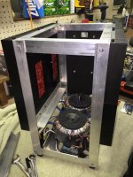
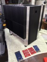
Also, i'm going to use all 8 of the original heat sinks by framing the heatsink and faceplate with some angle aluminum. I'll flip the faceplate over in the final version so that the power switch is at the bottom.
I'll post on the other appropriate threads from here on. Is there a recommended thread to post progress ?
EDIT: for some reason the image wouldn't show proper orientation
Attachments
Last edited:
")
400mv bias unatainable ?
OK, Been a couple of months doing other things, and then the Holidays, but finally got back to the F5T, and all is looking great ... Except for Bias.
Rail Voltages are at +/- 42 VDC, exactly as expected with the transformers.
The Amp powers up fine, I used the Lamp Mains cord in lieu of a variac.
Cascoding on the FE board with Q7 and Q8 in place.
When I adjust P1 and P2, everything happens as it should, and I can slowly increase the bias with one pot (P1), while keeping the DC offset at 0 by then adjusting the other(P2), HOWEVER, I can only get the bias up to 44mv on one channel, and 37mv on the other, and that is AFTER removing Lamp Mains cord and using standard mains cable. It Seems that P2 runs out of turns first.
I have checked the resistor values, particurlarly r5 and r6, 1K, in parallel with P1, P2.
I tired a couple of times, and checked the 3 meters in other positions, to ensure that they were agreeing.
And of course, the amp is not warming up AT ALL.
Any thoughts ?
I had the same problem yesterday. I raised r5 and 6 to 2.2k.
http://www.diyaudio.com/forums/pass-labs/207103-f5-turbo-builders-thread-423.html
Post 4229
http://www.diyaudio.com/forums/pass-labs/207103-f5-turbo-builders-thread-423.html
Post 4229
Last edited:
Theoretical question.
I have 116-117V on main when I turn all my gear up (F5T mono-blocks, preamp, CD player or Phono with TT in case of vinyl play). when F5Ts are off, my main is 120VAC. I have 24V 900VA toroids and PSUs outs is 28VDC in F5Ts with MUR3020WT rectifiers. Maybe you can suggest some lower Vdrop rectifiers like Schottky type or/and SiC that I will not loose much Vout. I want to keep 32 Vout from PSU module.
I have 116-117V on main when I turn all my gear up (F5T mono-blocks, preamp, CD player or Phono with TT in case of vinyl play). when F5Ts are off, my main is 120VAC. I have 24V 900VA toroids and PSUs outs is 28VDC in F5Ts with MUR3020WT rectifiers. Maybe you can suggest some lower Vdrop rectifiers like Schottky type or/and SiC that I will not loose much Vout. I want to keep 32 Vout from PSU module.
Your main's electricity supply to your socket outlets is broken.Theoretical question.
I have 116-117V on main when I turn all my gear up (F5T mono-blocks, preamp, CD player or Phono with TT in case of vinyl play). when F5Ts are off, my main is 120VAC. ................
Get an Electrician to sort it.
Your main's electricity supply to your socket outlets is broken.
Get an Electrician to sort it.
Hi Andrew,
I do not think so. I exaggerated with 116VAC.
All my gear connected to that 15A line and I usually see 118-120VAC with no load, and 117VAC min when all is connected.
Any way, I was supposed to use 25VAC trany instead of my 24VAC. Too late now for trany exchange and this why I'm looking for low Vf rectifiers.
I have 24V 900VA toroids and PSUs outs is 28VDC in F5Ts with MUR3020WT rectifiers.
Using a 1.6kVA 24VAC transformers and the same diodes, I see 33VDC rails when the amps are biased to about 2A per channel.
This is quad secondaries with 4 bridges, so the Vdrop is a little higher than a single bridge. 5V sounds too high of a difference that cannot be explained by the drop in primary AC.
I also agree with AndrewT that you need to have a check on the mains wiring. 2V over 120V is close to 1.5% regulation with under 500W load. It sounds very, very wrong. I would understand if it was a big storage heater or similar, but any amplifier, even a F5T at full tilt, should not cause such a big constant drop (maybe while turn-on a little dip is normal).
You need to check the actual AC voltage at your secondary, not what is on the label. Maybe that will give some clue as to the source of your issue.
Hi Andrew,
I do not think so. I exaggerated with 116VAC.
All my gear connected to that 15A line and I usually see 118-120VAC with no load, and 117VAC min when all is connected.
Any way, I was supposed to use 25VAC trany instead of my 24VAC. Too late now for trany exchange and this why I'm looking for low Vf rectifiers.
Just for comparison I have around 123V on my line and around 121.5 when both my F5TV3's monos are on and running.
nash
- Home
- Amplifiers
- Pass Labs
- F5Turbo Illustrated Build Guide