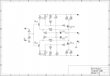
Thanks for looking Juma, attached the schematic with values as used. Only difference that I haven't incorporated are the input network values (51k/249 ohm), and a few small values such as gate stoppers (56 ohm). The key front end parts are almost identical to your original schematic in the first post, except the feedback network. The 150 ohm resistors are 3W, and the 22 ohm and 2.7k resistors are 1/2w. The 2K is a 1W Holco, because I had them on hand.
Basically now that I've drawn it I see the two B-E voltages are superimposed across the 150 ohm resistors, the series combination is in parallel to the B-E junctions. 1.2V across 300 ohm is almost exactly the 4mA that I am seeing on the meters. The max resistance I can set using the pot is 1.15k, if I remove the 2K resistor I can probably get this to approx 2.4k. Would you say it's worth a shot? This should yield 7.5V of bias with the same 3mA, which should be sufficient. However I don't know if it sufficient to properly drive the output device.
Or, do I need to revise the feedback network values again (please don't say yes, those Dales are very pricey!!) or can I get away with increasing the bias in the FE?
Attachments
Last edited:
The values I gave were calculted for +/-24V psu and you have less than +/-20V ... Also, lower resistance in the feedback network will draw more current. Combine those two factors and you have a problem.
With Vgs of output MOSFETS being only 3.5V it's obvious that you need more current through the input stage so decrease R14/15 from 2k7 to 2k2 or 1k8 and see what you get (don't change the feedback network values, just increase the current through the input stage).
Also, with 22R in feedback, C1 and C2 should be 4700uF if you want good bass response.
If you want to have 51k at the input your BJTs will have to be nicely matched or you'll have substantial DC offset at the input (which is not important if you use input cap).
Last edited:
Thanks for the insights, will try to increase the current by using 1.8k resistors. Should I also try and remove the 2K resistor in the collector circuit?
I do have some caps on order, is the rolloff still calculated in the standard 2x3.14xRxC? I was looking at some 2700uF which would yield corner frequency of 2.7Hz. However I do have some cheap and chirpy 4700uF caps in case the value is non-negotiable, maybe will need a small parallel cap for decent midrange and treble with those in the feedback net.
On the input mismatch causing offset, won't the trimmers be used to null that out anyway? Sorry if I'm missing something here. The problem is that the BC550 and BC560 we use are from different manufacturers (NOS parts are unobtanium here) so chances of a good match are non-existent. I was able to bias fine with zero offset at the output and input when the original feedback net values (4k7/249R) were used, btw. There was no issue in basic operation, sonics notwithstanding.
I shall also try a higher voltage supply before making changes in the PCB. I have an appropriate transformer that should be good for 25V rails and about 1A bias per channel.
NoShould I also try and remove the 2K resistor in the collector circuit?
It's not just about frequency but also about phase response - that's why I wrote:"If you want good bass..." . Just read carefully what I wrote.I do have some caps on order, is the rolloff still calculated in the standard 2x3.14xRxC?...
Read again - I wrote:" input DC offset". The trimmers will set the output DC offset. Input DC offset can make your volume pot squeak or damage your source component.On the input mismatch causing offset, won't the trimmers be used to null that out anyway? Sorry if I'm missing something here.
You are sweating it too much. Just change those two resistors.The problem is.... I shall also try ...
Hi
This worked out very nicely indeed. I put a set of 3.3k resistors in parallel with the existing 2.7k, and changed the feedback caps to 4700uF. Also used a small 100nF film cap in parallel as the big caps are not very good. The input pair gets warm but still in the early 50s. No input offset either, so guess I was lucky!
Biases up really well and sounds great, still trying to find the limits of my heatsink and power supply so I have them running slightly underbiased. I don't have the original F5 on hand to compare but this sounds just as good as my memory of that amp.
Thanks for the help, much appreciated!


Congratulation Sangram. Can you post a picture.Hi
This worked out very nicely indeed. I put a set of 3.3k resistors in parallel with the existing 2.7k, and changed the feedback caps to 4700uF. Also used a small 100nF film cap in parallel as the big caps are not very good. The input pair gets warm but still in the early 50s. No input offset either, so guess I was lucky!
Biases up really well and sounds great, still trying to find the limits of my heatsink and power supply so I have them running slightly underbiased. I don't have the original F5 on hand to compare but this sounds just as good as my memory of that amp.
Thanks for the help, much appreciated!
I have no doubt that it sounds great.
From post 18 I had built a headphone amplifier based on this circuit and about one month ago I have decided to build a small power amp of 15w/8 ohms with about 10w/8 ohms in class A. The main differences are the output trannies that are 2sk1530/2Sj201 and but current sources instead of simple resistors for bias of input transistors so it is more insensible to power supply sagging for output DC bias.
I like the sound very much and for me a lot better than my F5 since it is more "lively" and better control on the bass even though my power supply is about half the capacity of my F5 (now sold). I have named this new amplifier USSA( ultra simple symmetrical amplifier) and Any resemblance to the names such as VSSA or TSSA is a ....pure coincidence....


Enjoy your new amp Sangram!
Fab
Congratulation Sangram. Can you post a picture.
I have no doubt that it sounds great.
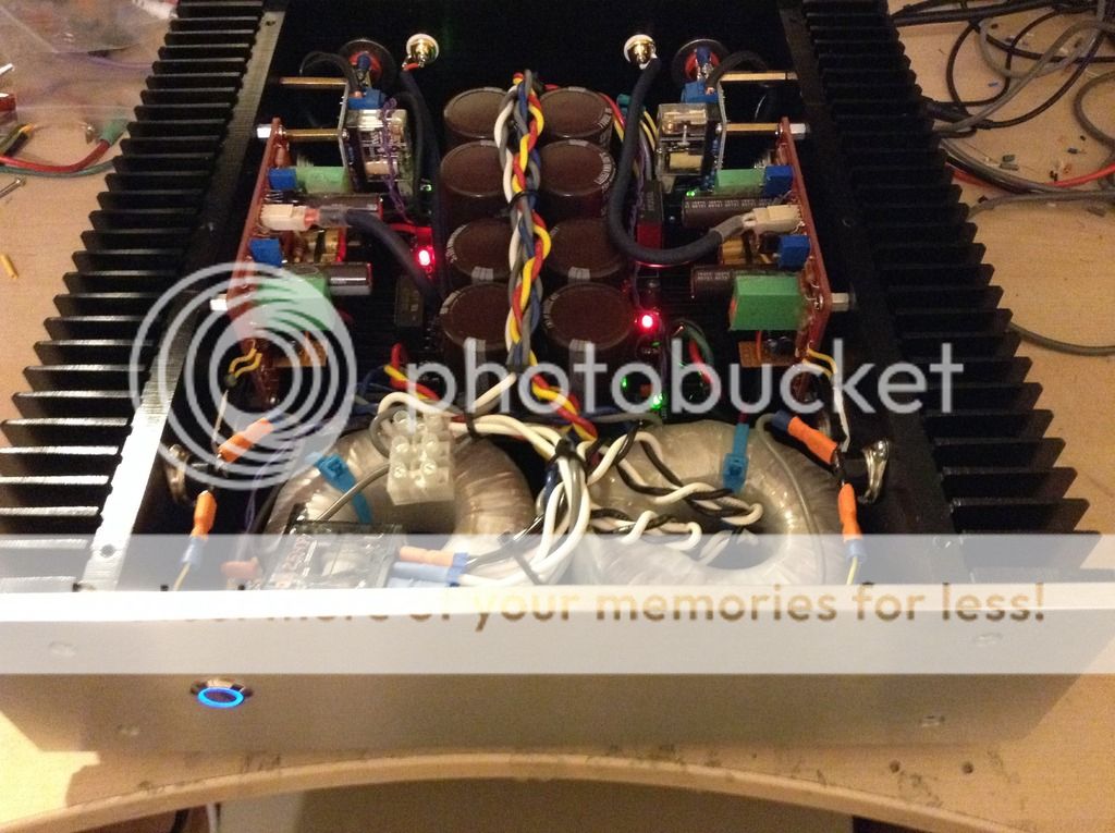
Your amp looks killer
My amp looks nothing like yours. It's not even in a case but mounted on a block of wood, has two fans for cooling a very small heatsink, and runs off a pair of laptop SMPS which are also fully naked so that they can deal with high load continuously,
The fan arrangement blows a bit of cool air over the supplies as well, and as a result nothing crosses 45 degree temperatures. Since the supply voltage is on the lower side, I adjust the bias to deliver Class A output of about 20W, around 1.1A. The supplies have to deliver 2.2A total for two channels, and as long as they have a small amount of airflow they deal with it just fine. Never felt lack of power.
I think let's keep my pictures out of the thread unless there was one for how bad an amp could look. I basically built it to be able to carry under one arm for other people to listen to in their setups, to understand what a good amplifier can do, and as a test amp for speaker and source design and evaluation. A portable unit is much more convenient than one weighing 15 kilos. For reference, I weigh 53 kilos.
I find there is absolutely silent output even with ear to the cone and 90-92dB speakers. I don't know why this is so, I was expecting some HF ripple, but there is none at all. Of course since the SMPS are regulated there is no sag in PSU voltage even at full bias. My total power supply capacitance is 3,000uF per rail. No problem with bass though, it's nice and solid. Using with Zaph Audio L18 standmounts as their long-term partner.
I have a problem with output devices after one blew and the substitutions do not work correctly, so am waiting for some new matched devices to come in at the end of June. Before that though it sounded great.
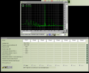
What I will do is attach a picture of the test results, which look a lot better than the amp itself! I guess I may have been slightly clipping the input, because I was able later to get the H2 down to about -85dB and vanishing traces later. Ignore the bumps in the lower frequency, that is due to ground loop because the input and output are connected to the same physical device with no isolator. I shall update results after I get new devices and a working amp.
Attachments
Hello Eric,
These are off-the shelf units purchased locally for $5.50 each.
They are standard laptop chargers with rated output of 65W, 18.5V, 3.52 A. I think they say 'HP' on the label but they are not. These are made in some cheap factory in China.
I use a heating tool to open the case and replace the capacitors on both sides, the input side gets a 100uF/400V long-life Hitachi cap instead of the shockingly poor 47uF stock unit, and for the secondary side 1000uF caps to replace the standard 330uF. The SMPS has two of them, and the resulting capacitance is about the highest they will be happy with. Also I use a small ceramic in parallel, which is not used in the standard unit.
Two of these are connected in series. Your supplies need to be of the fully isolated variety, because if the negative output is connected to mains earth you cannot use the supplies in series. There are ways around the issue, but those are both dangerous and illegal. Do note th main issue with fully isolated units is that they are actually not so, There is a small capacitor between the two negative sides of the transformer to prevent charge buildup in the output. as a result, a mains tester will light up when connected to the output. But no hazardous voltage is present/current can flow as the cap is very small (I think 2nF).
The supplies are operated at under 65% max output, which is absolutely within spec and if you have a small amount of airflow, it runs very cool indeed. The ones I bought were very cheap and the main compromise was the capacitor quality. Fixing that basically sorted out the performance issues completely. And they are excellent partners for Class A amps in general if the output is quiet enough. As you can see, the noise level in high frequency is below -110dB.
Nice amp Fab, congrats !
Maybe one day I'll drop by for a visit and threat my ears for a party !
BR,
Eric
Thanks Eric, you are welcome to visit me!
Fab
Your amp looks killer
My amp looks nothing like yours. It's not even in a case but mounted on a block of wood, has two fans for cooling a very small heatsink, and runs off a pair of laptop SMPS which are also fully naked so that they can deal with high load continuously,
The fan arrangement blows a bit of cool air over the supplies as well, and as a result nothing crosses 45 degree temperatures. Since the supply voltage is on the lower side, I adjust the bias to deliver Class A output of about 20W, around 1.1A. The supplies have to deliver 2.2A total for two channels, and as long as they have a small amount of airflow they deal with it just fine. Never felt lack of power.
I think let's keep my pictures out of the thread unless there was one for how bad an amp could look. I basically built it to be able to carry under one arm for other people to listen to in their setups, to understand what a good amplifier can do, and as a test amp for speaker and source design and evaluation. A portable unit is much more convenient than one weighing 15 kilos. For reference, I weigh 53 kilos.
I find there is absolutely silent output even with ear to the cone and 90-92dB speakers. I don't know why this is so, I was expecting some HF ripple, but there is none at all. Of course since the SMPS are regulated there is no sag in PSU voltage even at full bias. My total power supply capacitance is 3,000uF per rail. No problem with bass though, it's nice and solid. Using with Zaph Audio L18 standmounts as their long-term partner.
I have a problem with output devices after one blew and the substitutions do not work correctly, so am waiting for some new matched devices to come in at the end of June. Before that though it sounded great.
What I will do is attach a picture of the test results, which look a lot better than the amp itself! I guess I may have been slightly clipping the input, because I was able later to get the H2 down to about -85dB and vanishing traces later. Ignore the bumps in the lower frequency, that is due to ground loop because the input and output are connected to the same physical device with no isolator. I shall update results after I get new devices and a working amp.
Thanks Sangram.
It doesn't matter if your amp is not in a case. I also makes prototypes and I found it useful to see how people's do prototypes with simple means. But you do what you want of course.
On my part, I thought it can be interesting to show that a 15W with 10w in class A amp can fit in a small enclosure 12" x12" ( exterior).
Thanks for sharing the distortion spectrum.
Fab
ClassA does not equal constant current on the supply rails.............info about your SMPS, I like to use them for Class A amp and being a heavier but constant load it's easy for SMPS.
When output current is equal to maximum ClassA, then you will find that the current in the output stage supply rails varies from zero amperes to the peak ClassA current
The difference in current on the two supply rails equals the output current.
i.e. when one supply rail is at zero amperes and the other supply rail is at ClassA maximum, the output current is ClassA maximum. And then the supply rail currents swap over when the speaker current is in the opposite direction (alternating current).
On my part, I thought it can be interesting to show that a 15W with 10w in class A amp can fit in a small enclosure 12" x12" ( exterior).
Fab
This is quite impressing considering that your set-up is dual mono
Eric
Ecxellent
excellent circuit. Please upload congratulations on the diagram and pcb
Congratulation Sangram. Can you post a picture.
I have no doubt that it sounds great.
From post 18 I had built a headphone amplifier based on this circuit and about one month ago I have decided to build a small power amp of 15w/8 ohms with about 10w/8 ohms in class A. The main differences are the output trannies that are 2sk1530/2Sj201 and but current sources instead of simple resistors for bias of input transistors so it is more insensible to power supply sagging for output DC bias.
I like the sound very much and for me a lot better than my F5 since it is more "lively" and better control on the bass even though my power supply is about half the capacity of my F5 (now sold). I have named this new amplifier USSA( ultra simple symmetrical amplifier) and Any resemblance to the names such as VSSA or TSSA is a ....pure coincidence....
Enjoy your new amp Sangram!
Fab
excellent circuit. Please upload congratulations on the diagram and pcb
excellent circuit. Please upload congratulations on the diagram and pcb
Thanks!
You can see more details in this forum:
Amplificateur USSA 15W - Conception
I now have 4 versions of USSA. This one here is USSA-1. USSA-1 to 4 are using an F5 pcb with modifications done. But shortly I will present a dedicated pcb for USSA-5 which is a little more complicated version no more possible to build using an F5 pcb....the layout is being done at this moment and the pcb will be avalaible for the diyers in the near future after initial testing of performances.
However, if you want to build the version 1 or 2 on an F5 pcb then just send me your email by private message and I can provide you the build and adjustment instructions.
Fab
Last edited:
Anybody knows this Variant called BJT-F5 with BC550/560?
Last winter I build that one ,
all parts I purchased in Germany, so it was an easy and fast building.
Using parts for powersupply :
700VA/4x27V, Caps: 8x BHC 15000µF/63V/2x4 for dualpower.
Bias is 480mV like the F5Turbo, It was tricky tedius to bias it to reach the right
number on every site. For all wiring I used single-cor copper from coil.
Powerconsumption is 156W without playing music.
Soundwise that thing is breathtaking... never heard an orginal F-5 or other Pass products.
Preamp is Waynes DIYaudio one. Pre and Poweramp are working exellent together.
Attachments
Last edited:
- Home
- Amplifiers
- Pass Labs
- F5 with BJT at input