To avoid cap multiplier with this amp is wrong choice (and you'll be disappointed). If you want more power and more output pairs the design has to be changed.... power supply will stay at 23 V for more power
It's easy to try and see what you prefer.... do you recommend corection of feedback resistors 100//100 with various number pairs and values for Rs
To avoid cap multiplier with this amp is wrong choice (and you'll be disappointed). If you want more power and more output pairs the design has to be changed.
I already got 4 times more capacitance In PS than stoke amp
I found huge improvement with cap multiplier - I suggest to make it as it is inexpensive and easy. Look here for more details.
http://www.diyaudio.com/forums/solid-state/297921-jumas-easy-peasy-capacitance-multiplier.html
http://www.diyaudio.com/forums/solid-state/297921-jumas-easy-peasy-capacitance-multiplier.html
Sure,
i wish you a successful build.
I understand what that means

XRK,
would you please compare sound perception between cap multiplier and CRC
Last edited:
FET Matching
Acquiring the parts, and thinking about this project forever, and now finally getting it going!
Got the fets ages ago from Prakit, and did some matching the other day. Do these all look pretty good and normal? Measured at 4 points manually. 20 pairs of each. Table Attached.
View attachment fetsMatch.pdf
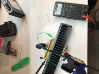
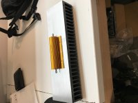
Disippation Test
Also, did some disippation tests with my heatsinks. I was aiming for 3 pairs @ 350ma at 19V = ~40 W. But I seem to be a bit light on the sinks.
I mounted a power resistor to the sink and ran 41w through it. Bloody hot! After 1 hour, I can only hold my hand on it for 3-5 seconds. I think it's too hot.
I did some other tests, and it seems like if I can get to around 30-32 W I should be fine.
Sooo, what would be the best sounding compromise?
1) Run 3 pairs @ 300ma @ 18V
2) Run 2 pairs @ 400ma @16V
3) other suggestions?
I should mention that my speakers are these:
Tonian Labs TL-D1 - speakers - [English]
Driver is Fostex FE207E
My other amp is a push pull 6v6, that puts out ~8W, and it is PLENTY loud. I'd be happy with a 12V peak output voltage from this amp.
Attachments
Last edited:
Looks all right.... Do these all look pretty good and normal?
1) will work all right, be patient in adjustment process, wait for it to get hot and check once more when you put the lead on the case.... what would be the best sounding compromise?
1) Run 3 pairs @ 300ma @ 18V
2) Run 2 pairs @ 400ma @16V
3) other suggestions? ...
2) not a great idea
3) get bigger heatsink
Your testing/measuring is being done on single devices.Acquiring the parts, and thinking about this project forever, and now finally getting it going!
Got the fets ages ago from Prakit, and did some matching the other day. Do these all look pretty good and normal? Measured at 4 points manually. 20 pairs of each. Table Attached.
View attachment 623945
I suggest you select pairs that look close and test them as a pair attached to a heatsink.
Then monitor the Id (Vrd) of both as you adjust the Vgs.
This is effectively copying the installation in your build where the same voltage is applied to all the Nchannel devices attached to the same heatsink and you hope all devices will pass the same current.
Great, thanks for the advice and tips above.
I'll go for three pairs then, and target around 32-33W. But one question:
I can arrive at that target a variety of ways.
For example
300ma * 6 * 18V
OR
350ma * 6 * 15.5V.
What is the theoretical downside to lower voltage at the rails? From reading the main F5 thread, I read about gate capacitance. But in looking at the datasheet, I see only a very very slight increase in Ciss going from 20 to 15V. Coss seems to go up from around 30pf to 35pF as the voltage is decreased, but is this significant?
Are there are other factors that contribute to decreased performance as the voltage is dropped from lets say to 20 to 15V?
Of course, power goes down by dropping the rail V, but in my case, I'm not concerned about that.
I'm really curious about this technical detail, so thanks in advance for all responses.
If output power is of no concern then you shouldn't shun the lower rails/higher Id version.
Great, and thanks! I'm going to target 15-16V @ 350-375ma with 3 pairs. Will adjust as necessary once I get it set up.
One last question before I place my order for parts:
With the lower rails, do I need to adjust any of the other parts values? For example R3-R6 around the Jfet inputs?
F5x is a lower supply voltage, higher bias current version of the F5.
Worth reading some of the Thread.
Thank you. I hadn't followed that thread at all. Will take a look.
No. You can experiment with with MOSFETs' Source resistors - some prefer the way it sounds with 0R33 instead of 0R68... do I need to adjust any of the other parts values? ...
Hi Juma,
I've simulated the circuit in Ltspice, FFT looks very good but square wave had some ringing.
So I added some compensation caps over the feedback resistors (C1,C2), result: perfect squares
But this is only simulation, what's your advice about adding such compensation caps ?
In the sim I used the 9610/710 because I didn't find any models of the 2SK2013/2SJ313
Regards,
Danny
Attachments
Last edited:
Some Progress
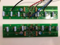
Ok, so I've made some progress. Boards stuffed.
The hardest part I always find is the metalwork. I already broke my only two 4-40 taps (~M3 x.5) trying to tap the heatsinks So I dropped them off to a friend who has a drill press and is a little better at that part.
Two questions while I wait for sinks back.
1) With the FETs not installed yet, can I test the rest of the circuit? I'd like to at least check the Jfet stage to make sure it is all working right.
2) Is the gain of this amp the same as the regular F5 (15 db)? I'm using .47 source resistors in case that matters.
Thanks,
Ok, so I've made some progress. Boards stuffed.
The hardest part I always find is the metalwork. I already broke my only two 4-40 taps (~M3 x.5) trying to tap the heatsinks
So I dropped them off to a friend who has a drill press and is a little better at that part.Two questions while I wait for sinks back.
1) With the FETs not installed yet, can I test the rest of the circuit? I'd like to at least check the Jfet stage to make sure it is all working right.
2) Is the gain of this amp the same as the regular F5 (15 db)? I'm using .47 source resistors in case that matters.
Thanks,
Attachments
The hardest part I always find is the metalwork. I already broke my only two 4-40 taps (~M3 x.5) trying to tap the heatsinks
Always use cutting oil, it makes tapping much easier.
Tacking onto the post above... one of my projects has the end of a drill bit still in it. Use plenty of oil... go slow... throw drill bits away when they don't cut so well anymore. Always drill the pilot hole deeper than you think you'll need to, all things permitting. Nothing more aggravating than "tapping out" your tap. Been there...
- Status
- This old topic is closed. If you want to reopen this topic, contact a moderator using the "Report Post" button.
- Home
- Amplifiers
- Pass Labs
- F5 with 2SK2013/2SJ313