Not all have your beautiful boards")
Thank you
I could give you the Gerber files. So you could do your own boards.
Thank you
I could give you the Gerber files. So you could do your own boards.
Can you post the Gerbers and/or the PDFs?
Power supply question
Hi Juma,
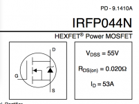
For this power supply Novi amp sa 2SK2013/2SJ313 - Stranica 2 - Solid State - diyAudio.rs (and attached), I wanted to confirm that the source of the IRFP044N is on the transformer side of the rails (because maybe the symbol is backwards?).
Is it better to use four huge capacitors instead of paralleling smaller ones in this circuit? (. . . just wondering, since there's lots of people on the forum filling up the middle of their amps with 1000s of small caps, etc.) Dd you use the 1uF film caps shown on the schematic (C1-C4), and, if so, what did you use?
Thanks, David (a/k/a "moving ahead at a snails pace. . . ")
p.s. Also, I wanted to express my thanks for all of the cool projects you have posted here over the years, and for being such a great teacher.
Hi Juma,
For this power supply Novi amp sa 2SK2013/2SJ313 - Stranica 2 - Solid State - diyAudio.rs (and attached), I wanted to confirm that the source of the IRFP044N is on the transformer side of the rails (because maybe the symbol is backwards?).
Is it better to use four huge capacitors instead of paralleling smaller ones in this circuit? (. . . just wondering, since there's lots of people on the forum filling up the middle of their amps with 1000s of small caps, etc.) Dd you use the 1uF film caps shown on the schematic (C1-C4), and, if so, what did you use?
Thanks, David (a/k/a "moving ahead at a snails pace. . . ")
p.s. Also, I wanted to express my thanks for all of the cool projects you have posted here over the years, and for being such a great teacher.
Attachments
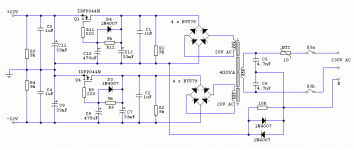
Nothing is backward there and sources are not "on the transformer side" (whatever that might mean since the only parts on the transformer side are rectifier bridges). Actually, I'm not sure at all what are you supposing/asking here but let's put it this way:I wanted to confirm that the source of the IRFP044N is on the transformer side of the rails (because maybe the symbol is backwards?).
IRFP044 is N-channel MOSFET and as such it needs its Drain to be on higher potential than the Source in order to operate. For example, in the sch. you quote, the Source of Q1 is at +22V and the Drain is at about +26V. That schematic is a bit unusual since it uses N-channel MOSFETs for both positive and the negative rail but don't get confused, just make it exactly as drawn and you'll be ok (as long as you are able to distinguish source from the drain - be careful about that).
I used 4 big Panasonic caps (33mF/35V) and 1uF Philips MKC (as drawn in sch.)Is it better to use four huge capacitors instead of paralleling smaller ones in this circuit? ...
A lot of smaller caps might give bigger total ripple current but unpredictable impedance situation (crazy resonant peaks) are possibility too.
Whatever path you choose to follow, make sure you use good quality caps. I've listened to version of this amp made with cheap chinese PSU caps (which were tested good on Sencore LC103 cap & coil analyzer) and it sounded intolerably dull...
......... I wanted to confirm that the source of the IRFP044N is on the transformer side of the rails (because maybe the symbol is backwards?). .........
All vertical mosFETs have the Drain pin in the middle and connected to the rear mounting plate.Nothing is backward there and sources are not "on the transformer side" (whatever that might mean since the only parts on the transformer side are rectifier bridges). Actually, I'm not sure at all what are you supposing/asking here but let's put it this way:
IRFP044 is N-channel MOSFET and as such it needs its Drain to be on higher potential than the Source in order to operate. For example, in the sch. you quote, the Source of Q1 is at +22V and the Drain is at about +26V.............
The Middle Pin (of an N channel vFET) goes to the higher +ve voltage.
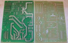
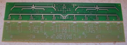
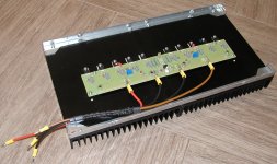
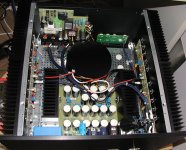
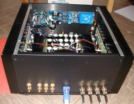
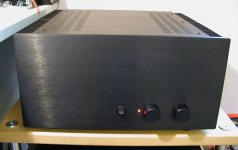
I'd like to share few pictures of my first amp based on F5 Juma version 1 with 5 instead of 3 output mosfet pairs. I also added into the same housing Juma preamp and my sofswitch/DC offset filter/AC filter PCB. What is missing is a final version of input selector and volume control.
Attachments
Great job prasimix 
Just two things:
- make sure to listen to your amp with 3 and with 5 output pairs - it won't sound the same...
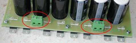
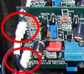
- you made a great project and it hurts me to see that you use the dish-washer/lawn-mower style connections inside it. Those connectors (see attachment) have no place in serious audio equipment (unsatisfying electromechanical properties and compromised long term reliability). Let your soldering iron do that...
Just two things:
- make sure to listen to your amp with 3 and with 5 output pairs - it won't sound the same...
- you made a great project and it hurts me to see that you use the dish-washer/lawn-mower style connections inside it. Those connectors (see attachment) have no place in serious audio equipment (unsatisfying electromechanical properties and compromised long term reliability). Let your soldering iron do that...
Attachments
Juma,
are you telling us that spade terminals are good, or bad, for audio?
Or
Are you telling us that screw down terminals are good, or bad, for audio?
I believe juma is referring to the spades as per his photo.
I also prefer to solder all the connections between boards and as little as possible. It might not make a difference in sound, but if one excludes a bunch of solder points and different metal connections from a build it can't hurt! KISS I think!
Screw-down terminals can be tolerated on big filter caps because those are big strong screws that you can rely on to maintain tight and firm connection.
Spades are good for nothing serious. Household and low-grade industrial appliances uses them in equipment that is not meant to last beyond warranty expiration date.
Spades are good for nothing serious. Household and low-grade industrial appliances uses them in equipment that is not meant to last beyond warranty expiration date.
Exactly.I believe juma is referring to the spades as per his photo.
Great job prasimix
Just two things:
- make sure to listen to your amp with 3 and with 5 output pairs - it won't sound the same...
- you made a great project and it hurts me to see that you use the dish-washer/lawn-mower style connections inside it. Those connectors (see attachment) have no place in serious audio equipment (unsatisfying electromechanical properties and compromised long term reliability). Let your soldering iron do that...
Thanks Juma for your design and comments. This work clearly shown that I'm more then beginner in this field, but ok, that's frequently connected with DIY concept. I find that such dish-washer (
) thing is very practical in testing phase when you need to move and change things. I also didn't have idea (practice) how to handle all that stuff which is heavy with cables soldered on both side. Maybe I can put at least on one side connectors which I used for AC inputs on power supply PCB (see picture). Or maybe is better to spend some more time and solder everything back to back. I presume that same thing is applicable on preamp side (see another picture) where I used small Molex 0.1" connectors.Regarding outputs: what is your recommendation 3 or 5 pairs?
Some other thing that I find troublesome:
- Rectifier diode require real heatsinks (currently I have around 70 degrees Celsius on them, or that is "real case"?).
- My toroidal transformer is only 450VA and it's pretty audible with such continuous load (maybe I should go with 600 or 700VA or maybe another 450VA or downsize output to 3 pairs per channel?)
- Good grounding strategy is a paramount, each amp module with short-circuited inputs are very quiet, but anything added to it can easily add unacceptable level of hum (50Hz). I have now low level of such hum but still think that it could be better since as I mentioned before amp modules alone are very silent. Any suggestion about this topic is more then welcomed.
Attachments
I avoid any type of (re)movable connections - I don't trust them. IME only nice, soldered joint is a good joint - everything else opens the gates of disaster. As with anything else, there is an easy path, and there is a correct path - the amp and the choices are yours only...
I prefer 3 pairs in output stage - you can easily test different number of devices to find your preference.
1. For rectifier diodes I use small heatsinks or bolt them to the bottom of the case - 50-60 degrees C on them is OK.
2. 450VA is plenty - if your transformer vibrates it's a bad transformer, not a small transformer (try DC blocker, it might help).
3.Work on your grounding scheme and try rotating/moving the transformer to eliminate hum. That amp is totally silent when made correctly (I built 4 of them with repeatable and reliable performance).
I avoid any type of (re)movable connections - I don't trust them. IME only nice, soldered joint is a good joint - everything else opens the gates of disaster. As with anything else, there is an easy path, and there is a correct path - the amp and the choices are yours only...
I prefer 3 pairs in output stage - you can easily test different number of devices to find your preference.
1. For rectifier diodes I use small heatsinks or bolt them to the bottom of the case - 50-60 degrees C on them is OK.
2. 450VA is plenty - if your transformer vibrates it's a bad transformer, not a small transformer (try DC blocker, it might help).
3.Work on your grounding scheme and try rotating/moving the transformer to eliminate hum. That amp is totally silent when made correctly (I built 4 of them with repeatable and reliable performance).
6.3mm spades are long-time reliable connectors. I do use them in my amp builds since more than 30 years without any failure.
There must be good reason, why they are applied in extremely demanding automotive applications, for example.
BTW, thank you very much for sharing your nice F5 interpretation
I'd like to share few pictures of my first amp based on F5 Juma version ...
nice clean amp
is this the first build we see here ?
your boards look different from the GB boards
nice clean amp
is this the first build we see here ?
your boards look different from the GB boards
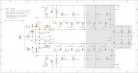
I missed GB so I made my version (inspired by Permaneder design). It can be used for up to 5 output pairs (Juma said 3 is way to go) and can be used for Juma's Ver 1 and Ver 2. See schematic in attachment.
Attachments
I avoid any type of (re)movable connections - I don't trust them. IME only nice, soldered joint is a good joint - everything else opens the gates of disaster. As with anything else, there is an easy path, and there is a correct path - the amp and the choices are yours only...
I prefer 3 pairs in output stage - you can easily test different number of devices to find your preference.
Thanks, I'll try to test that somehow.
1. For rectifier diodes I use small heatsinks or bolt them to the bottom of the case - 50-60 degrees C on them is OK.
I'm using perforated steel plate as heat sink, but obviously is not so effecient as dedicated alu heatinks.
2. 450VA is plenty - if your transformer vibrates it's a bad transformer, not a small transformer (try DC blocker, it might help).
Hm, that's interesting, I'll need to talk with manufacturer (garage enterprise). DC blocker is on the softstart PCB and don't helps a lot here.
3.Work on your grounding scheme and try rotating/moving the transformer to eliminate hum. That amp is totally silent when made correctly (I built 4 of them with repeatable and reliable performance).
I agree, amp module alone is very silent. Here is definitely room for improvement.
Some other thing that I find troublesome:
Rectifier diode require real heatsinks (currently I have around 70 degrees Celsius on them, or that is "real case"?).
My toroidal transformer is only 450VA and it's pretty audible
try Toroidy/Poland
switching power diodes needs a good heatsink
and I would not use the smaller 8A diodes
though ...
snerring trafo, and hot diodes ... ? ... sure it's not caused by oscillation ?
try Toroidy/Poland
Thanks for recommendation.
I'm using STTH2002DI (20A/200V)switching power diodes needs a good heatsink
and I would not use the smaller 8A diodes
though ...
snerring trafo, and hot diodes ... ? ... sure it's not caused by oscillation ?
Maybe, but both transformer buzz and diode's temp rise with load as expected (no load, no trouble).
- Status
- This old topic is closed. If you want to reopen this topic, contact a moderator using the "Report Post" button.
- Home
- Amplifiers
- Pass Labs
- F5 with 2SK2013/2SJ313