If each Fet can handle 12 amps full load, then derating to 60% for longevity gives you a max of 7.2 amps/FET. That's and additional 1.2 amps x 4 fets *the other 4 are off*. Which is 4.8 amps or an extra 240 VA.
70% is 8.4 amps/FET => 2.4 * 4 = 9.6 amps or an extra 480 VA. That is a 1080 VA transformer.
Derating to 80 % gives your 9.6 amps/FET, or an extra 4 x 3.6 = 14.4 amps or 720 VA for a total of 1320 VA.
Looking at this backwards, if you have a 1500 va transformer, you've got 900 VA above 150 watt class A. 900 / 4 = 225 VA /FET = 4.5 amps. Which means that each FET can push 10.5 amps steady state, which only derates to 10.5/12 = 87.5 percent.
I'm not so sure this is a good idea. It is looking like a 1KVA transformer is about the max you want to supply to this sort of monoblock.
I would use 4 amp/ fet for SOA ....
BigE,Sanity check time for me....
V3, 4 pairs per channel, biased to 3,0 amps per polarity, 50 volt rails. That gives 0,75 watts/FET, or 0,35 Volts. Total bias current is 6 amps.
Now total dissipation is 8 * 50 * 0.75 = 300 watts. That can easily be spread over 4 regular sized F5 heatsinks at 75 watts per heat sink -- each heatsink carries one pair of FETS.
Efficiency is around 33% at full class A power. Does that sound about right?
As for Transformer VA, clearly 300 VA is needed just to run the bias. Now, add the load requirements. P=150 rms = 300 peak.
So, P=IV , V = 50 says I = 6 amps peak. That is another 300 VA to power class A operation. (That checks with doubling the bias current to come out of class A).
So far, the transformer has to be 600 VA *bare minimum*.
What do you spec for Class A/B overhead? Do you limit the VA to provide 50% of the steady state operating current of the output transistors?
Also, how do the diodes impact the heatsink size?
I don't know where you found your references, but most of what you have posted is plain wrong.
The total bias current is 3A. The rail to rail voltage is 100Vdc. The dissipation is 300W. You got the correct answer using rubbish data.
A 300VA 37+37Vac will get your +-50Vdc supply rails when supplying about 2Adc. Let's check: 300VA & 35+35Vac results in a rated current of 4.05Aac.
This will give a maximum continuous dc current from the capacitor input filter of ~2Adc. You cannot and must not draw 3Adc from a 300VA transformer.
For that continuous current draw of 3Adc, you must use a transformer rated @ 6Aac i.e. 444VA.
Now to your next fallacy.
A +-50Vdc 3A bias ClassA amplifier when delivering zero Watts to the load consumes 300W as shown earlier. When it delivers ClassA current to the load, the total load seen by the pSU does not change. If 20W goes to the load the amp dissipates the remaining 280W. If 50W goes to the load, the amp dissipates the remaining 250W.
if 100W goes to the load, then 200W is dissipated by the amplifier.
Why is this so?
Because the rail currents are not constant. as one rail current increases the other rail current decreases by exactly the same amount. The difference in rail currents goes to the load. The total load seen by the PSU does not change.
Now that I have settled that, lets go back to transformer VA.
A 444VA transformer delivering 3Adc continuously will run hot. As hot as the manufacturer allows for their product.
For cooler running and good reliability it is generally recommended that the continuous DC current drawn be approximately 50% of the manufacturer's specified maximum continuous DC current when feeding a capacitor input filter.
This would require a transformer rated @ 800VA to 900VA.
This has nothing to do with delivering ClassA power to the load. This is simply to allow reliable and cooler operation than the manufacturer's maximum rating while the amplifier is idling.
As stated earlier when the amplifier is delivering ClassA power the total load seen by the transformer stays the same. You don't need any extra VA for ClassA power delivery.
If you want more power than ClassA then the amplifier transitions to ClassAB and the power drawn by the amplifier becomes the average for A ClassAB with high bias when delivering high output currents.
The usual factor to apply is roughly 1 to 2 times the maximum output power as a VA value.
Lets suppose your ClassA is 140W and you decide that the maximum ClassAB should be double this, i.e. 280W. This would require a 280VA to 560VA transformer. But we need to make an adjustment for the high bias. 444VA for high bias + 1.5*280W for ClassAB on a continuous basis is an overestimate for required VA. This indicates that a 864VA would be the upper limit for needed VA for the ClassAB amplifier. Same as for a cooler running transformer.
Now look at the normal range of VA suggested by Pass and others. Use about 6times to 10times the maximum ClassA output power. For a 140W amplifier 6 times comes out at 840VA, and 10times indicates 1400VA.
Your
does not give much assistance to any builder.the transformer has to be 600 VA *bare minimum*.
Even the 6 to 10 times is a better guide.
The logic you followed in later posts is also flawed. By luck you appear to be getting closer to a real transformer rating
Peak current to the load comes from the capacitors.
It has very little to do with average currents supplied to keep the capacitors charged.
Last edited:
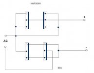
Hi Blink,I'll build the PSU to F5T 2 in a board made by me, but there is a doubt on the links of MUR3020W!
Thanks to confirm that the connections are correct. thank you
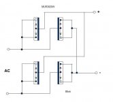
This is the correct connetions
An externally hosted image should be here but it was not working when we last tested it.
Last edited:
Hi Blink,
This is the correct connetions
.......
Hello Carlomar,
It will be more explicit way. The problem will be passing it to the PCB. I'll wear clothes iron, and paper photocopy laser... (half dozen copies)
Attachments
Hi Blink,
This is the correct connetions
.......
Hello Carlomar,
It will be more explicit way. The problem will be passing it to the PCB. I'll wear clothes iron, and paper photocopy laser... (half dozen copies)
It is easy with 2 layer PCB. See how I made it for 4 blocks, you are referring one of them.


Last edited:
It is easy with 2 layer PCB. See how I made it for 4 blocks, you are referring one of them.
View attachment 317360
View attachment 317361
View attachment 317362
They are all the same, change the color? The rectifiers in this scheme are separated from PSU?
What is the value of the capacitors connected will bridge?
Saw its construction in Hifivision and really liked...
They are all the same, change the color? The rectifiers in this scheme are separated from PSU?
What is the value of the capacitors connected will bridge?
Saw its construction in Hifivision and really liked...
Thanks ! First one is two layer PCB (red+blue), second is top layer(red) only and third is bottom layer (blue) only. All these layers are shown where diode pins are connected to specific layers only - either top or bottom.
Caps across diodes are 0.1uF, 100V film caps. This will connect to CRC filter board where each rail of single channel will have 4X 15000uF, 50V caps. There will be total 4 of above in stereo amp.
Last edited:
buzz. a little undersizedi will say 600VA is minimum for a V2
This bought it very cheap, has 600VA and has only an output of 24V, 50A.
PSU will connect as NP has in the scheme, only has two voltage wires, the wire does not have middle of the mass ...
Is it better to go for a 800VA?
Is 1KVA sufficient for two channels?
I will have 32V rails with 1A bias per device - that should be about 250W standing dissipation with 4 outputs per channel..
Based on a quick calculation from Andrew's excellent post, I am guessing I'll be OK or just about OK.
Note that what AndrewT posted was for 1 channel at 50V rails.
Just a brief glance (I didn't do the full calculation.) the fact that your running 4A bias per channel you may be at the cusp 1KVA being ok.
Is 1KVA sufficient for two channels?
I will have 32V rails with 1A bias per device - that should be about 250W standing dissipation with 4 outputs per channel..
Based on a quick calculation from Andrew's excellent post, I am guessing I'll be OK or just about OK.
Sangram,
I am wiring up a V3 with exact same Toroid specs as yours, due for completion next week. I am quite unsure of the PSU caps, as I ran into ripple related hum problems on V2 with 8 x 10000 uF, 50V caps per rail. In V3, I am planning to use 16 caps of 15000uF, 63V CDE per channel. Hope they are sufficient.
Cheers.
According to Andrews post -- ONE CHANNEL:
For a continuous draw of 4 amps, you need an 8 x 64 = 512 VA. Then multiply this by two for reliable operation, and you've got 1Kva for the single channel at this bias.
So 2KVA, is needed for a stereo amp with 4 amps bias per channel using 32 V rails. You are off by a factor of two.
For a continuous draw of 4 amps, you need an 8 x 64 = 512 VA. Then multiply this by two for reliable operation, and you've got 1Kva for the single channel at this bias.
So 2KVA, is needed for a stereo amp with 4 amps bias per channel using 32 V rails. You are off by a factor of two.
- Home
- Amplifiers
- Pass Labs
- F5 Turbo Builders Thread